Chapter 5
Connection Equipment and Specifications
2.A
When using the
3.
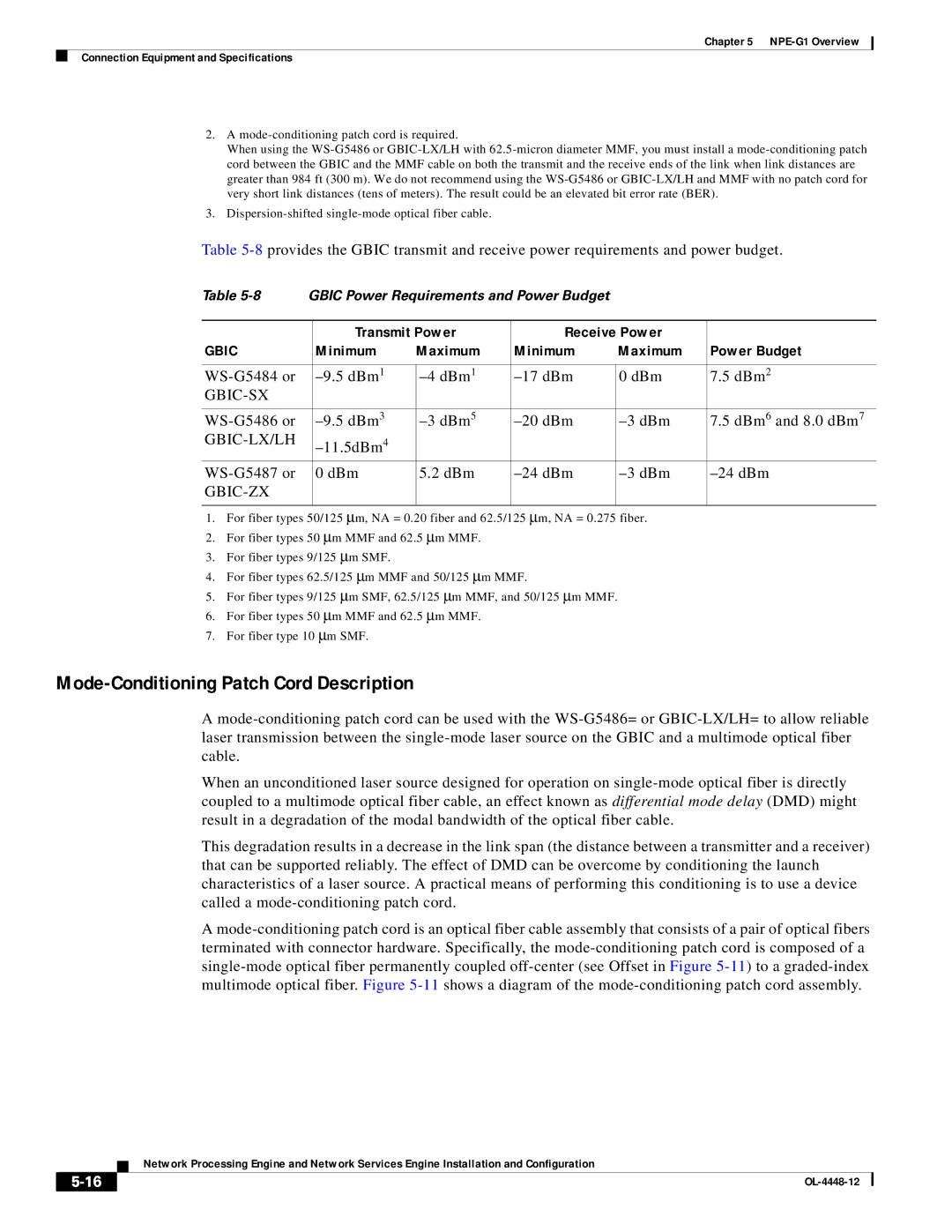
Table
Table | GBIC Power Requirements and Power Budget |
|
|
| |||
|
|
|
|
|
|
|
|
|
| Transmit Power | Receive Power |
|
| ||
GBIC |
| Minimum | Maximum | Minimum | Maximum | Power Budget | |
|
|
|
|
|
|
|
|
| 0 dBm | 7.5 dBm2 |
| ||||
|
|
|
|
|
|
| |
|
|
|
|
|
|
|
|
| 7.5 dBm6 | and 8.0 dBm7 | |||||
|
|
|
|
|
|
| |
| 0 dBm | 5.2 dBm |
| ||||
|
|
|
|
|
|
| |
|
|
|
|
|
|
|
|
1.For fiber types 50/125 μm, NA = 0.20 fiber and 62.5/125 μm, NA = 0.275 fiber.
2.For fiber types 50 μm MMF and 62.5 μm MMF.
3.For fiber types 9/125 μm SMF.
4.For fiber types 62.5/125 μm MMF and 50/125 μm MMF.
5.For fiber types 9/125 μm SMF, 62.5/125 μm MMF, and 50/125 μm MMF.
6.For fiber types 50 μm MMF and 62.5 μm MMF.
7.For fiber type 10 μm SMF.
Mode-Conditioning Patch Cord Description
A
When an unconditioned laser source designed for operation on
This degradation results in a decrease in the link span (the distance between a transmitter and a receiver) that can be supported reliably. The effect of DMD can be overcome by conditioning the launch characteristics of a laser source. A practical means of performing this conditioning is to use a device called a
A
Network Processing Engine and Network Services Engine Installation and Configuration
|
| |
|
