Chapter 7
Copying the Saved Configuration to NVRAM
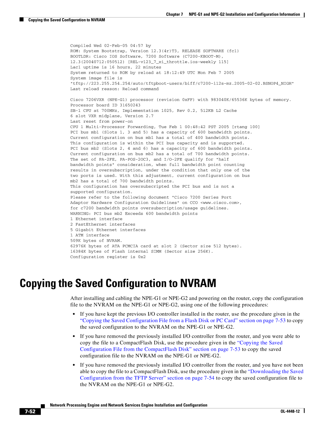
Compiled Wed
ROM: System Bootstrap, Version 12.3(4r)T3, RELEASE SOFTWARE (fc1)
BOOTLDR: Cisco IOS Software, 7200 Software
System returned to ROM by reload at 18:12:49 UTC Mon Feb 7 2005 System image file is
Cisco 7206VXR
Last reset from
CPU 1
PCI bus mb2 (Slots 2, 4 and 6) has a capacity of 600 bandwidth points. Current configuration on bus mb2 has a total of 700 bandwidth points. The set of
This configuration has oversubscripted the PCI bus and is not a supported configuration.
Please refer to the following document "Cisco 7200 Series Port Adaptor Hardware Configuration Guidelines" on CCO <www.cisco.com>, for c7200 bandwidth points oversubscription/usage guidelines. WARNING: PCI bus mb2 Exceeds 600 bandwidth points
1 Ethernet interface
2 FastEthernet interfaces
5 Gigabit Ethernet interfaces
1 ATM interface
509K bytes of NVRAM.
62976K bytes of ATA PCMCIA card at slot 2 (Sector size 512 bytes).
16384K bytes of Flash internal SIMM (Sector size 256K). Configuration register is 0x2
Copying the Saved Configuration to NVRAM
After installing and cabling the
•If you have kept the previous I/O controller installed in the router, use the procedure given in the “Copying the Saved Configuration File from a Flash Disk or PC Card” section on page
•If you have removed the previously installed I/O controller from the router, and you were able to copy the file to a CompactFlash Disk, use the procedure given in the “Copying the Saved Configuration File from the CompactFlash Disk” section on page
•If you have removed the previously installed I/O controller from the router, and you have not been able to copy the file to a CompactFlash Disk, use the procedure given in the “Downloading the Saved Configuration from the TFTP Server” section on page
Network Processing Engine and Network Services Engine Installation and Configuration
|
| |
|