Chapter 9 Removing and Installing the NPE or NSE
Removing and Replacing the NPE or NSE
Installing DRAM SIMMs
The DRAM SIMMs on the network processing engine are located in the following sockets:
•U18, U25, U4, and U12 on the
•U11, U25, U42, and U52 on the
Caution Handle SIMMs by the edges only; avoid touching the memory modules, pins, or traces (the metal fingers along the connector edge of the SIMM). (See Figure
To install memory SIMMs in the network processing engine, complete the following steps:
Step 1 With the network processing engine in the same orientation as the previous procedure (with the handle away from you and the edge connector toward you), install the first SIMM in the socket farthest from you. Then install the last SIMM in the socket closest to you.
Step 2 Remove a new SIMM from the antistatic bag.
Note To prevent DRAM errors in the
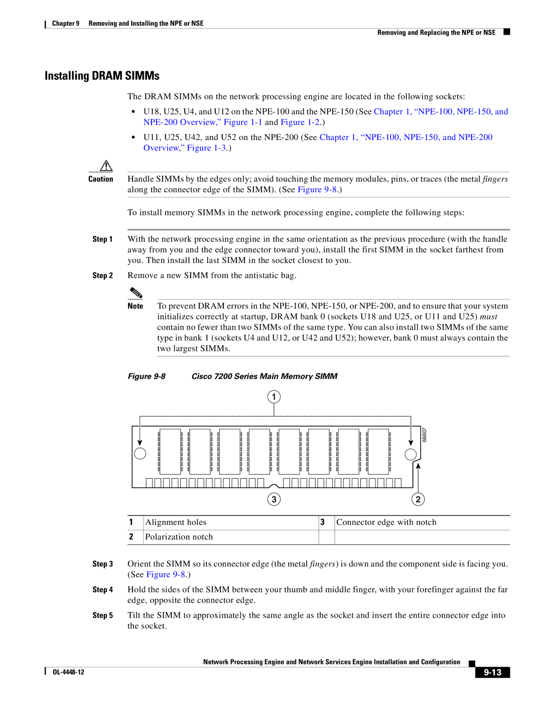
Figure 9-8 Cisco 7200 Series Main Memory SIMM
1
66607
1
2
3 | 2 | |||
Alignment holes |
| 3 |
| Connector edge with notch |
|
| |||
Polarization notch |
|
|
|
|
|
|
|
|
|
Step 3 Orient the SIMM so its connector edge (the metal fingers) is down and the component side is facing you. (See Figure
Step 4 Hold the sides of the SIMM between your thumb and middle finger, with your forefinger against the far edge, opposite the connector edge.
Step 5 Tilt the SIMM to approximately the same angle as the socket and insert the entire connector edge into the socket.
Network Processing Engine and Network Services Engine Installation and Configuration
|
| ||
|
|