Chapter 7
Installing the
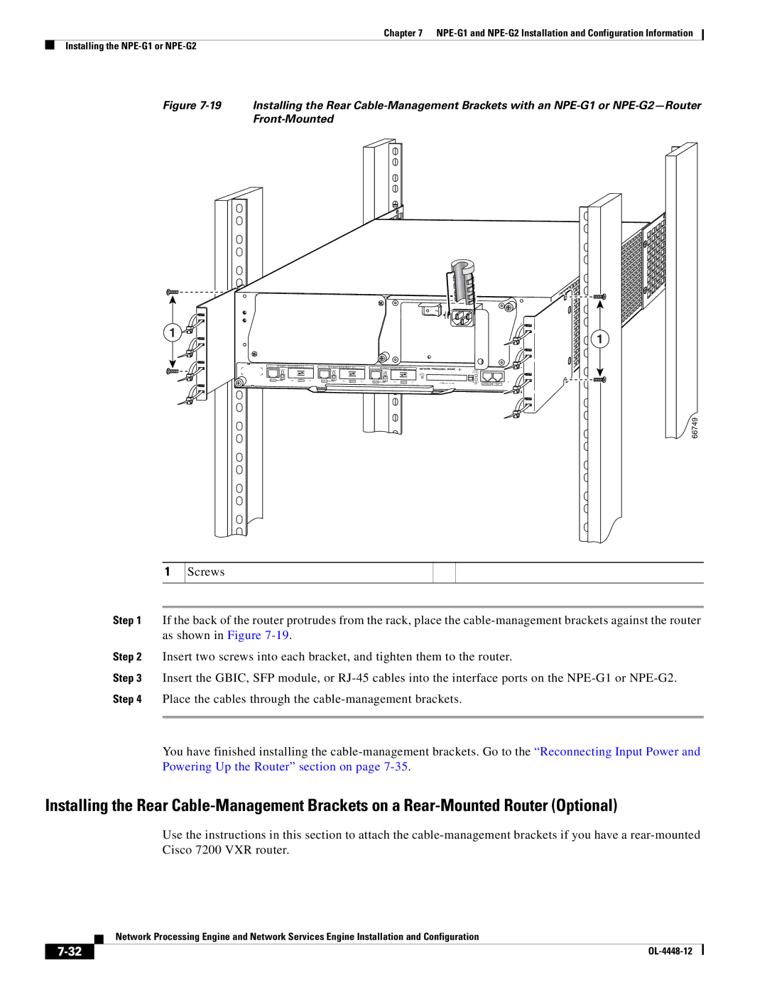
Figure 7-19 Installing the Rear Cable-Management Brackets with an NPE-G1 or NPE-G2—Router Front-Mounted
1![]()
G I G A B I T | E T H E R N E T 0 / 1 |
| G I G A B I T | E T H E R N E T 0 / 1 |
|
| G I G A B I T | E T H E R N E T 0 / 1 |
| NETWORK PROCESSING ENGINE |
|
| |||
L I N K |
|
|
|
|
|
| - | G1 | |||||||
|
|
| L I N K |
|
|
|
| L I N K |
|
|
| ||||
|
|
|
|
|
|
|
|
|
|
|
|
| C P U |
|
|
|
|
|
|
|
|
|
|
|
|
|
|
| R E S E T |
|
|
E N |
|
|
| E N |
|
|
|
|
|
|
|
|
|
|
|
R J 4 5 | R X | G B I C | T X | R J 4 5 | R X | G B I C | T X | R J 4 5 | E N | R X | G B I C | T X | C O M PA C T F L A S H |
|
|
S L O T |
|
|
A C T I V E |
|
|
POWER | CONSOLE | AUX |
OK |
![]()
![]() H6423
H6423![]()
![]()
![]()
![]() 1
1
66749
1
Screws
Step 1 If the back of the router protrudes from the rack, place the
Step 2 Insert two screws into each bracket, and tighten them to the router.
Step 3 Insert the GBIC, SFP module, or
You have finished installing the
Installing the Rear
Use the instructions in this section to attach the
Network Processing Engine and Network Services Engine Installation and Configuration
|
| |
|