Chapter 2
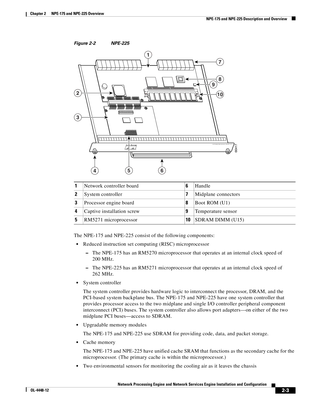
Figure |
|
1
7
8
9
2 | 10 |
3
|
|
|
| NETWORK PROCESSING | 66417 |
| 4 | 5 | 6 |
|
|
1 | Network controller board | 6 | Handle |
| |
2 | System controller |
| 7 | Midplane connectors | |
3 | Processor engine board | 8 | Boot ROM (U1) |
| |
4 | Captive installation screw | 9 | Temperature sensor | ||
5 | RM5271 microprocessor | 10 | SDRAM DIMM (U15) | ||
The
•Reduced instruction set computing (RISC) microprocessor
–The
–The
•System controller
The system controller provides hardware logic to interconnect the processor, DRAM, and the
•Upgradable memory modules
The
•Cache memory
The
•Two environmental sensors for monitoring the cooling air as it leaves the chassis
Network Processing Engine and Network Services Engine Installation and Configuration
|
| ||
|
|
