Chapter 7
Installing the
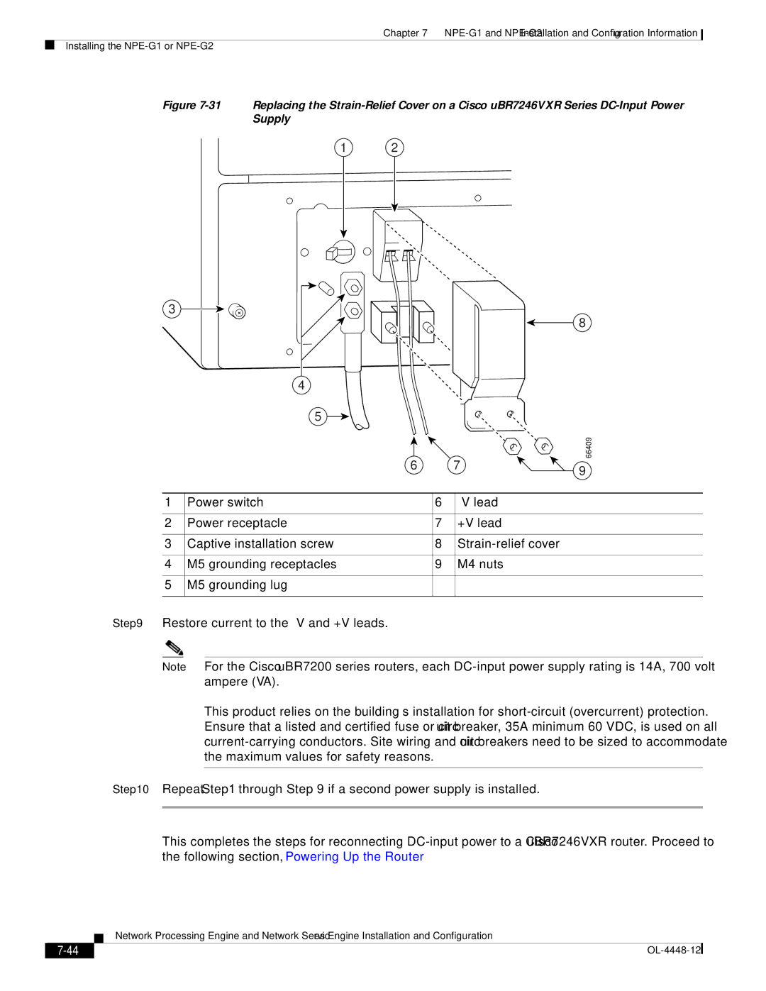
Figure 7-31 Replacing the Strain-Relief Cover on a Cisco uBR7246VXR Series DC-Input Power Supply
1 2
3
4
5
6
8
66409
7 | 9 |
|
1 | Power switch | 6 | |
|
|
|
|
2 | Power receptacle | 7 | +V lead |
|
|
|
|
3 | Captive installation screw | 8 | |
|
|
|
|
4 | M5 grounding receptacles | 9 | M4 nuts |
|
|
|
|
5 | M5 grounding lug |
|
|
|
|
|
|
Step 9 Restore current to the
Note For the Cisco uBR7200 series routers, each
This product relies on the building’s installation for
Step 10 Repeat Step 1 through Step 9 if a second power supply is installed.
This completes the steps for reconnecting
Network Processing Engine and Network Services Engine Installation and Configuration
|
| |
|