Chapter 5
–Three Gigabit Ethernet interfaces (six ports: three GBIC [optical] and three
–CompactFlash Disk for storing the default Cisco IOS software image. The CompactFlash Disk slot can be used whether or not an I/O controller is in the router.
–Auxiliary port with full data terminal equipment (DTE) functionality. (Functional when an I/O controller is not present. If an I/O controller is present, its auxiliary port is the default port.)
–Console port with full data communications equipment (DCE) functionality. (Functional when an I/O controller is not present. If an I/O controller is present, its console port is the default port.)
–Boot ROM for storing sufficient code for booting the Cisco IOS software.
–Flash memory for storing the boot helper (boot loader) image. (The boot helper image comes installed on the
–NVRAM for storing the system configuration and environmental monitoring logs. NVRAM uses lithium batteries to maintain its contents when disconnected from power. If an I/O controller is present, its NVRAM memory is no longer available.
–Upgradable memory modules
Note An I/O controller can be used with the
Interfaces and LEDs
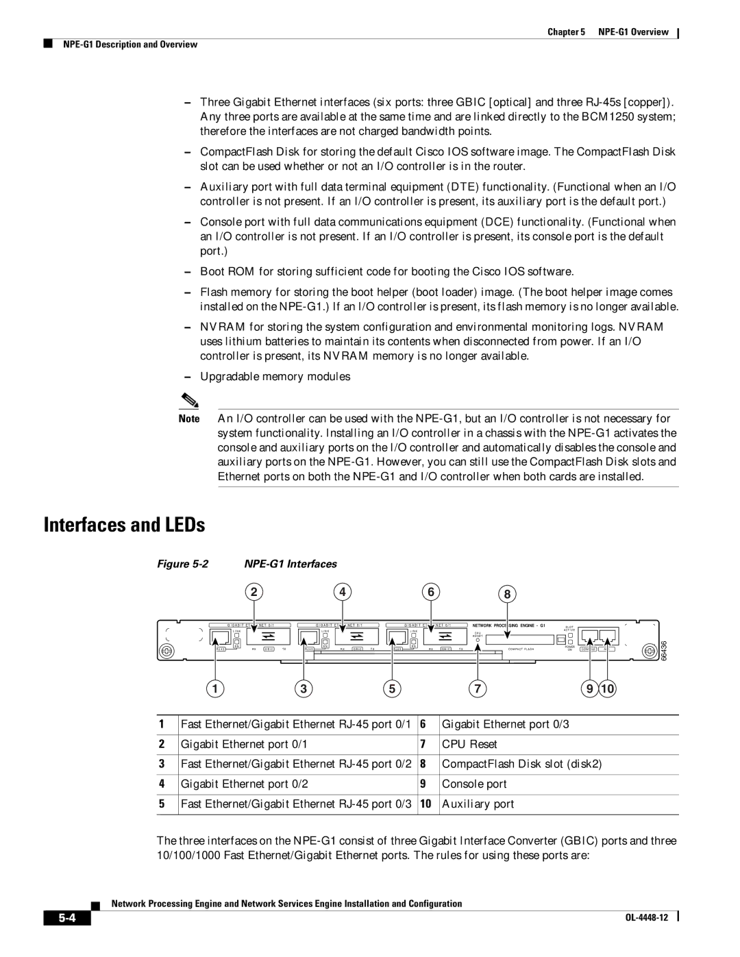
Figure 5-2 NPE-G1 Interfaces
2 | 4 | 6 | 8 |
G I G A B I T | E T | N E T 0 / 1 |
| G I G A B I T | E T | N E T 0 / 1 |
| G I G A B I T | E T | N E T 0 / 1 |
| NETWORK PROCESSING ENGINE - G1 |
L I N K |
|
|
| L I N K |
|
|
| L I N K |
|
|
| C P U |
|
|
|
|
|
|
|
|
|
|
|
| |
|
|
|
|
|
|
|
|
|
|
|
| R E S E T |
E N | R X |
| T X | E N | R X |
| T X | E N | R X |
| T X | C O M PAC T F L A S H |
R J 4 5 | G B I C | R J 4 5 | G B I C | R J 4 5 | G B I C | |||||||
1 |
|
|
| 3 |
|
|
| 5 |
|
|
| 7 |
S L O T |
|
|
A C T I V E |
|
|
POWER | CONSOLE | AUX |
ON |
9 10
66436
1 | Fast Ethernet/Gigabit Ethernet | 6 | Gigabit Ethernet port 0/3 |
|
|
|
|
2 | Gigabit Ethernet port 0/1 | 7 | CPU Reset |
|
|
|
|
3 | Fast Ethernet/Gigabit Ethernet | 8 | CompactFlash Disk slot (disk2) |
|
|
|
|
4 | Gigabit Ethernet port 0/2 | 9 | Console port |
|
|
|
|
5 | Fast Ethernet/Gigabit Ethernet | 10 | Auxiliary port |
|
|
|
|
The three interfaces on the
Network Processing Engine and Network Services Engine Installation and Configuration
|
| |
|
