Chapter 5
Connection Equipment and Specifications
The Cisco 7200 series routers ship with a
Table | Asynchronous Device Cabling Options |
| ||
|
|
|
| |
Access Server Port | End Device | |||
|
|
|
| |
Console or auxiliary | FDTE1 | Terminal | ||
Console or auxiliary | Straight | FDCE | Terminal | |
|
|
|
| |
Auxiliary or console | MMOD2 | Modem | ||
1.The FDTE
2.The MMOD
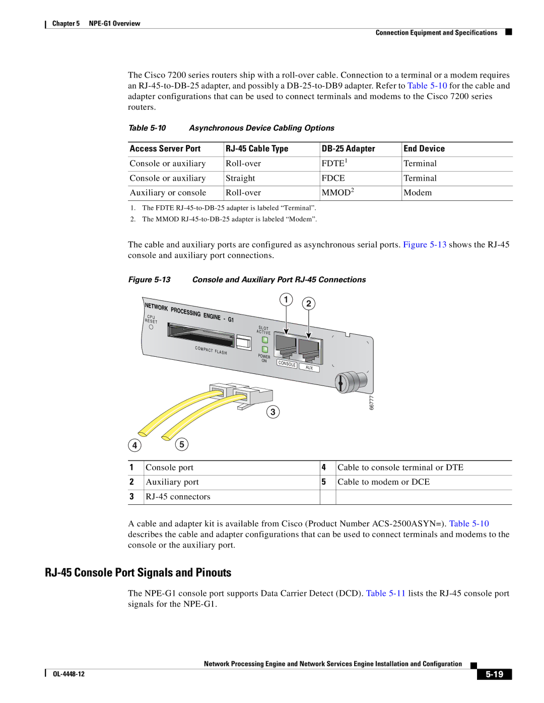
The cable and auxiliary ports are configured as asynchronous serial ports. Figure
Figure 5-13 Console and Auxiliary Port RJ-45 Connections
NETWORK
C P U
R E S E T
PROCESSING | ENGINE | - | G1 |
| |||
|
|
| |
|
|
| S L OT |
|
|
| A |
|
|
| C T I V E |
C O M |
|
| |
| PAC T |
|
|
| F L A S H | POWER | |
|
|
| |
|
|
| ON |
1 2
CONSOLE | AUX |
|
3
45
66777
1 | Console port | 4 | Cable to console terminal or DTE |
|
|
|
|
2 | Auxiliary port | 5 | Cable to modem or DCE |
|
|
|
|
3 |
|
| |
|
|
|
|
Acable and adapter kit is available from Cisco (Product Number
RJ-45 Console Port Signals and Pinouts
The
Network Processing Engine and Network Services Engine Installation and Configuration
|
| ||
|
|