Chapter 5
Connection Equipment and Specifications
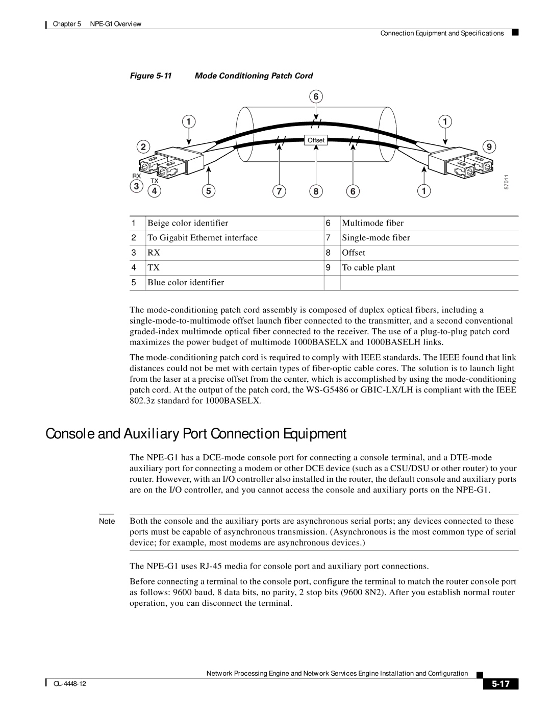
Figure | Mode Conditioning Patch Cord |
|
| ||||
|
|
|
| 6 |
|
| |
| 1 |
| / / | / / | / / | 1 | |
| 2 |
| Offset | 9 | |||
|
|
|
| ||||
|
|
|
|
| |||
RX | TX |
|
|
|
|
| |
3 |
|
|
|
|
| ||
4 | 5 | 7 | 8 | 6 | 1 | ||
| |||||||
57011
1 | Beige color identifier | 6 | Multimode fiber |
|
|
|
|
2 | To Gigabit Ethernet interface | 7 | |
|
|
|
|
3 | RX | 8 | Offset |
|
|
|
|
4 | TX | 9 | To cable plant |
|
|
|
|
5 | Blue color identifier |
|
|
|
|
|
|
The
The
Console and Auxiliary Port Connection Equipment
The
Note Both the console and the auxiliary ports are asynchronous serial ports; any devices connected to these ports must be capable of asynchronous transmission. (Asynchronous is the most common type of serial device; for example, most modems are asynchronous devices.)
The
Before connecting a terminal to the console port, configure the terminal to match the router console port as follows: 9600 baud, 8 data bits, no parity, 2 stop bits (9600 8N2). After you establish normal router operation, you can disconnect the terminal.
Network Processing Engine and Network Services Engine Installation and Configuration
|
| ||
|
|
