System board and components
ÊCarefully loosen the TPM screw using a thin slotted screw driver (e.g. watchmaker's screw driver) or the dedicated TPM screw driver (Japanese market) (2).
VCAUTION!
Ensure to turn the screw in the direction of the arrow in order to remove it!
Slowly and carefully increase the pressure on the screw until it begins to turn. The effort when loosing the screw should be as low as possible.
Otherwise the thin metal bar may break, rendering it impossible to loosen the screw.
ÊRemove the TPM screw (3).
ÊRemove the defective TPM board on the upper side of the system board.
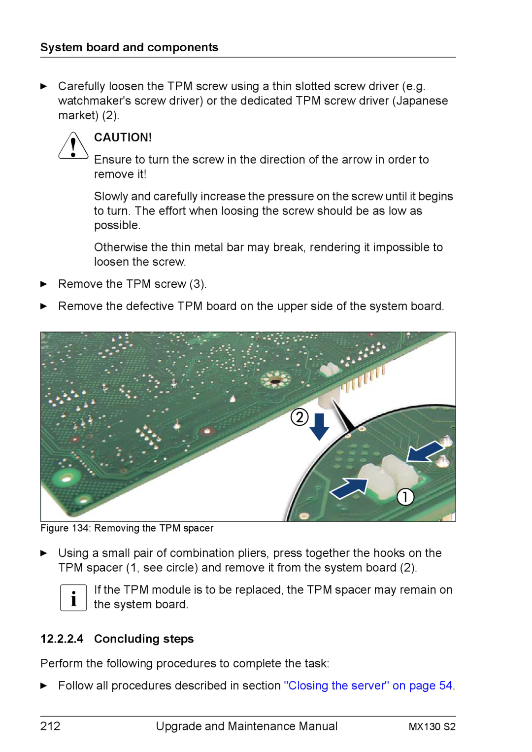
Figure 134: Removing the TPM spacer
ÊUsing a small pair of combination pliers, press together the hooks on the TPM spacer (1, see circle) and remove it from the system board (2).
IIf the TPM module is to be replaced, the TPM spacer may remain on the system board.
12.2.2.4 Concluding steps
Perform the following procedures to complete the task:
ÊFollow all procedures described in section "Closing the server" on page 54.
212 | Upgrade and Maintenance Manual | MX130 S2 |