|
|
|
| Main memory | |
|
|
|
|
| |
| Number of memory modules inserted | ||||
|
|
|
|
|
|
Slots to be used | 1 | 2 | 3 |
| 4 |
|
|
|
|
|
|
Slot 1, Channel A | o | o | o |
| o |
|
|
|
|
|
|
Slot 2, Channel B |
| o | o |
| o |
|
|
|
|
|
|
Slot 3, Channel A |
|
| o |
| o |
|
|
|
|
|
|
Slot 4, Channel B |
|
|
|
| o |
|
|
|
|
|
|
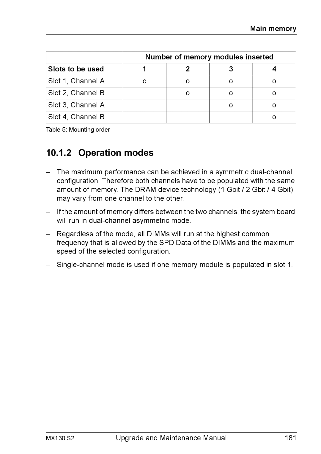
Table 5: Mounting order
10.1.2 Operation modes
–The maximum performance can be achieved in a symmetric
–If the amount of memory differs between the two channels, the system board will run in
–Regardless of the mode, all DIMMs will run at the highest common frequency that is allowed by the SPD Data of the DIMMs and the maximum speed of the selected configuration.
–
MX130 S2 | Upgrade and Maintenance Manual | 181 |
