Appendix
15.3Connectors and indicators
15.3.1 Connectors and indicators on the system board
15.3.1.1 Onboard connectors
PS2
USB 11+12
COM
Module 2 Channel B
Module 4 Channel B
Module 1 Channel A
Module 3 Channel A
POWER 12V
AM3/AM3+
CPU
POWER SATA
FRONT PANEL![]()
![]()
USB 9+10
LAN/
USB 7+8
Audio |
| (optional)optional) | ||
|
|
|
|
|
PCI
|
|
|
| FAN1 | |
|
|
|
| TPM | |
|
|
| SATA 5+6 | ||
|
| Northbridge |
|
| |
|
|
| Southbridge |
| |
|
|
|
| ||
Intrusion | Dash | 3/4 |
|
| |
SATA | |||||
| USB 5/6 | ||||
| 1/2 |
| 1+2 | ||
|
|
| |||
Super | FAN2 |
I/O |
Battery
SATA 3+4
Buzzer (optional)
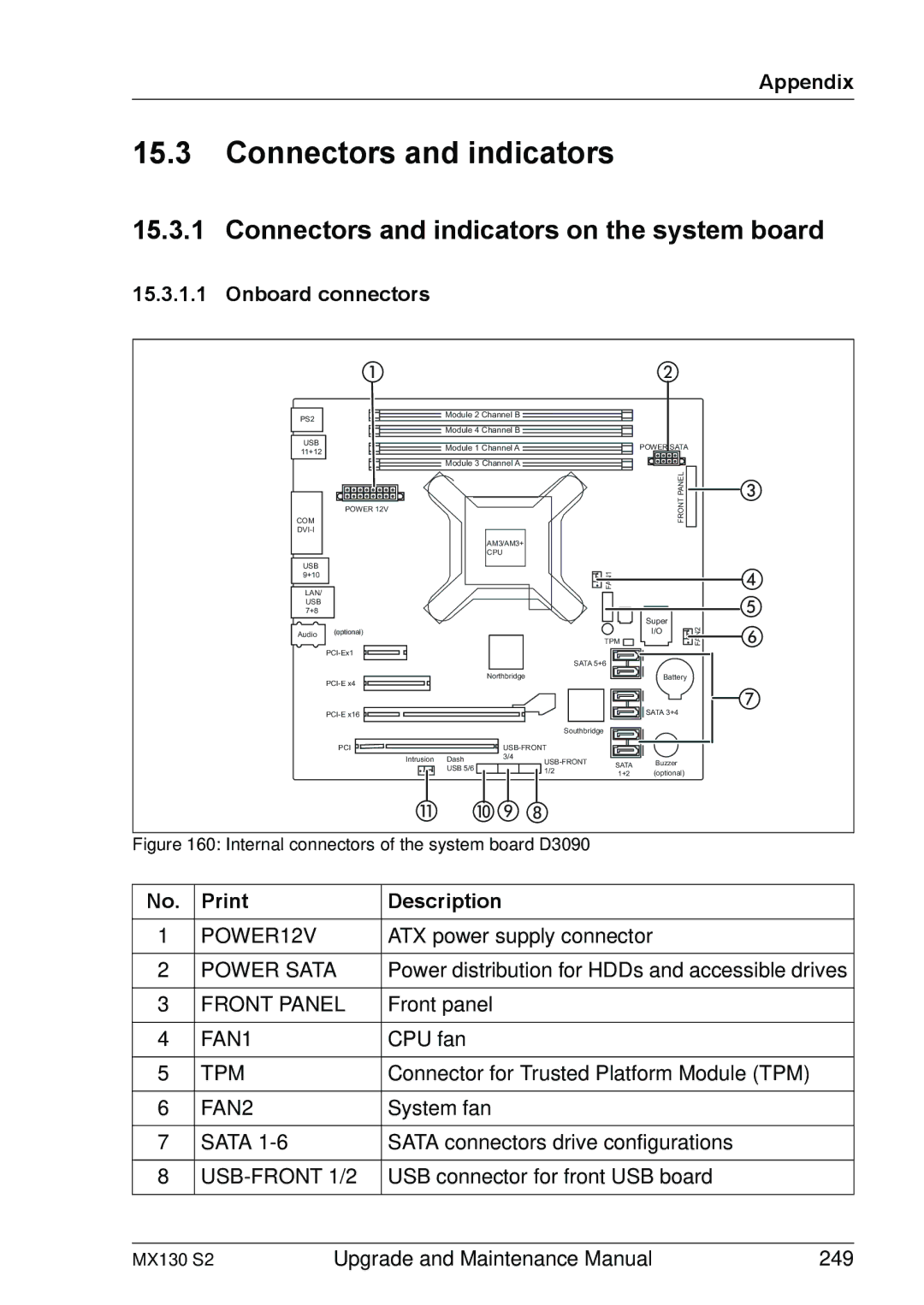
Figure 160: Internal connectors of the system board D3090
No. | Description | |
|
|
|
1 | POWER12V | ATX power supply connector |
|
|
|
2 | POWER SATA | Power distribution for HDDs and accessible drives |
|
|
|
3 | FRONT PANEL | Front panel |
|
|
|
4 | FAN1 | CPU fan |
|
|
|
5 | TPM | Connector for Trusted Platform Module (TPM) |
|
|
|
6 | FAN2 | System fan |
|
|
|
7 | SATA | SATA connectors drive configurations |
|
|
|
8 | USB connector for front USB board | |
|
|
|
MX130 S2 | Upgrade and Maintenance Manual | 249 |
