4 |
Assign Channel Status Vector (2000)
The Assign Channel Status Vector (ACSV) command specifies the location in local PLC CPU reference table memory of the
Example Command Block
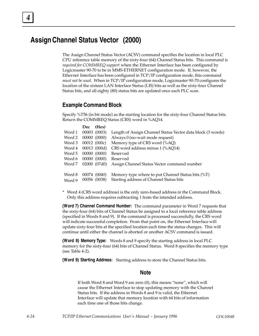
Specify %T56 (in bit mode) as the starting location for the
| Dec | (Hex) |
|
Word 1 | 00003 | (0003) | Length of Assign Channel Status Vector data block (3 words) |
Word 2 | 00000 | (0000) | Always 0 |
Word 3 | 00012 | (000c) | Memory type of CRS word (%AQ) |
Word 4 | 00013 | (000d) | CRS word address minus 1 (%AQ14) |
Word 5 | 00000 | (0000) | Reserved |
Word 6 | 00000 | (0000) | Reserved |
Word 7 | 02000 | (07d0) | Assign Channel Status Vector command number |
Word 8 | 00074 | (0040) | Memory type where to put Channel Status bits (%T) |
Word 9 | 00056 | (0038) | Starting address of Channel Status bits |
*Word 4 (CRS word address) is the only
(Word 7) Channel Command Number: The command parameter in Word 7 requests that the
(Word 8) Memory Type: Words 8 and 9 specify the starting address in local PLC memory for the
(Word 9) Starting Address: Starting address to store the Channel Status bits.
Note
If both Word 8 and Word 9 are zero (0), this means ªnoneº, which will cause the Ethernet Interface to stop updating memory with the Channel Status bits. If the address in Words 8 and 9 is valid, the Ethernet Interface will update that memory location with 64 bits of information each time one of those bits change.
TCP/IP Ethernet Communications User's Manual ± January 1996 |
|
