2 |
LEDS |
|
|
|
RESTART | B |
|
|
|
|
| |
PUSHBUTTON | A |
|
|
| T |
|
|
| T | MODEL 70 |
|
OPEN | E |
| |
R | CMM 741 |
| |
REPLACEMENT |
| ||
Y |
|
| |
BATTERY | MODULEOK |
| |
|
| ||
CONNECTOR |
| ONLINE |
|
|
| STATUSOK |
|
CURRENTLY |
| ON OR BLINK= OK |
|
INSTALLED |
| PUSH TO RESTART | |
BATTERY |
| ||
| LANINTERFACE. |
| |
CONNECTOR |
|
| |
| PUSH AND HOLD |
| |
|
|
| |
|
| TOREQUEST |
|
|
| LANINTERFACE |
|
9±PIN |
| DOWNLOAD. | INOP |
| WHENRUNNING |
| |
SERIAL |
|
| |
| DIAGNOSTICS |
| |
PORT |
|
| |
|
|
| |
|
| BATTERY |
|
|
| CONNECTIONS |
|
|
| INSTALL NEW |
|
|
| BATTERY BEFORE | |
15±PIN |
| UNPLUGGING OLD | |
|
| ||
ETHERNET |
| BATTERY. USE |
|
CONNECTOR |
|
| |
| IC697ACC701 |
| |
|
|
| |
|
| SERIAL |
|
|
| PORT |
|
|
| RS±232 |
|
|
| DTE |
|
|
| 2 TX (OUT) | |
|
| 3 RX (IN) |
|
|
| 7 GND |
|
DEFAULT |
|
|
|
STATION |
|
|
|
ADDRESS |
|
|
|
LABEL |
| PUSH |
|
|
|
| |
|
| SLIDEFROM |
|
|
| FRONTTO |
|
|
| LOCK:FROM |
|
|
| BACKTO |
|
|
| RELEASE |
|
|
| TRANSCEIVER | |
|
| CABLE |
|
|
| MODULE |
|
|
| IC697CCM741 |
|
|
| LABEL |
|
|
| 44A726758±117R01 | |
|
| GROUND | |
|
| WIRE | |
a44663
SERIAL
NUMBER
LABEL
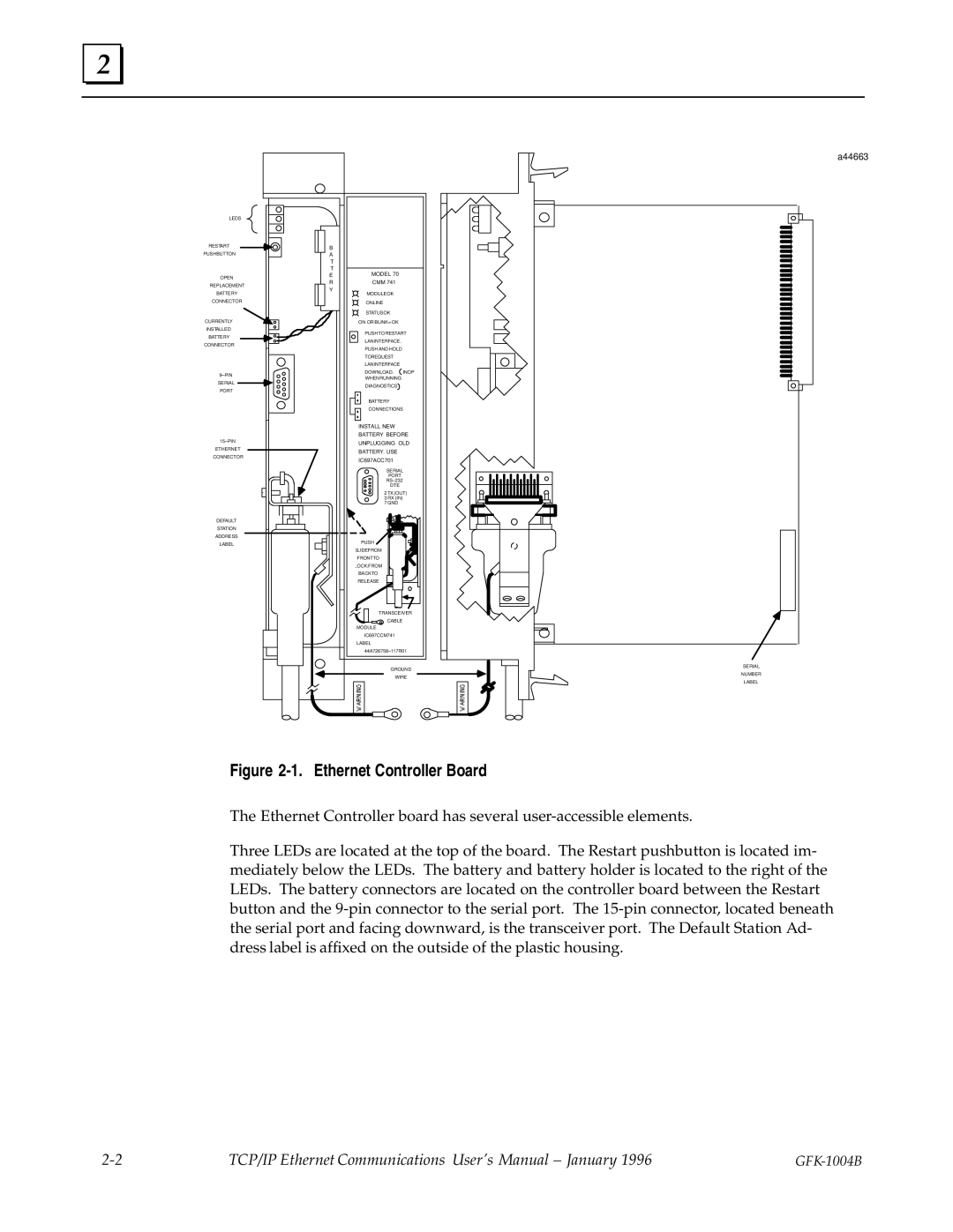
Figure 2-1. Ethernet Controller Board
The Ethernet Controller board has several
Three LEDs are located at the top of the board. The Restart pushbutton is located im- mediately below the LEDs. The battery and battery holder is located to the right of the LEDs. The battery connectors are located on the controller board between the Restart button and the
TCP/IP Ethernet Communications User's Manual ± January 1996 |