B |
Table B-1. Pinouts of the Serial Port
Pin Number | Signal | Description | |
1 | Shield | ChassisGround (optional) | |
2 | TXD | TransmitData(output) | |
3 | RXD | Receive Data (input) | |
7 | Common | SignalGround | |
(allothers) |
| Unused | |
|
Serial Cable
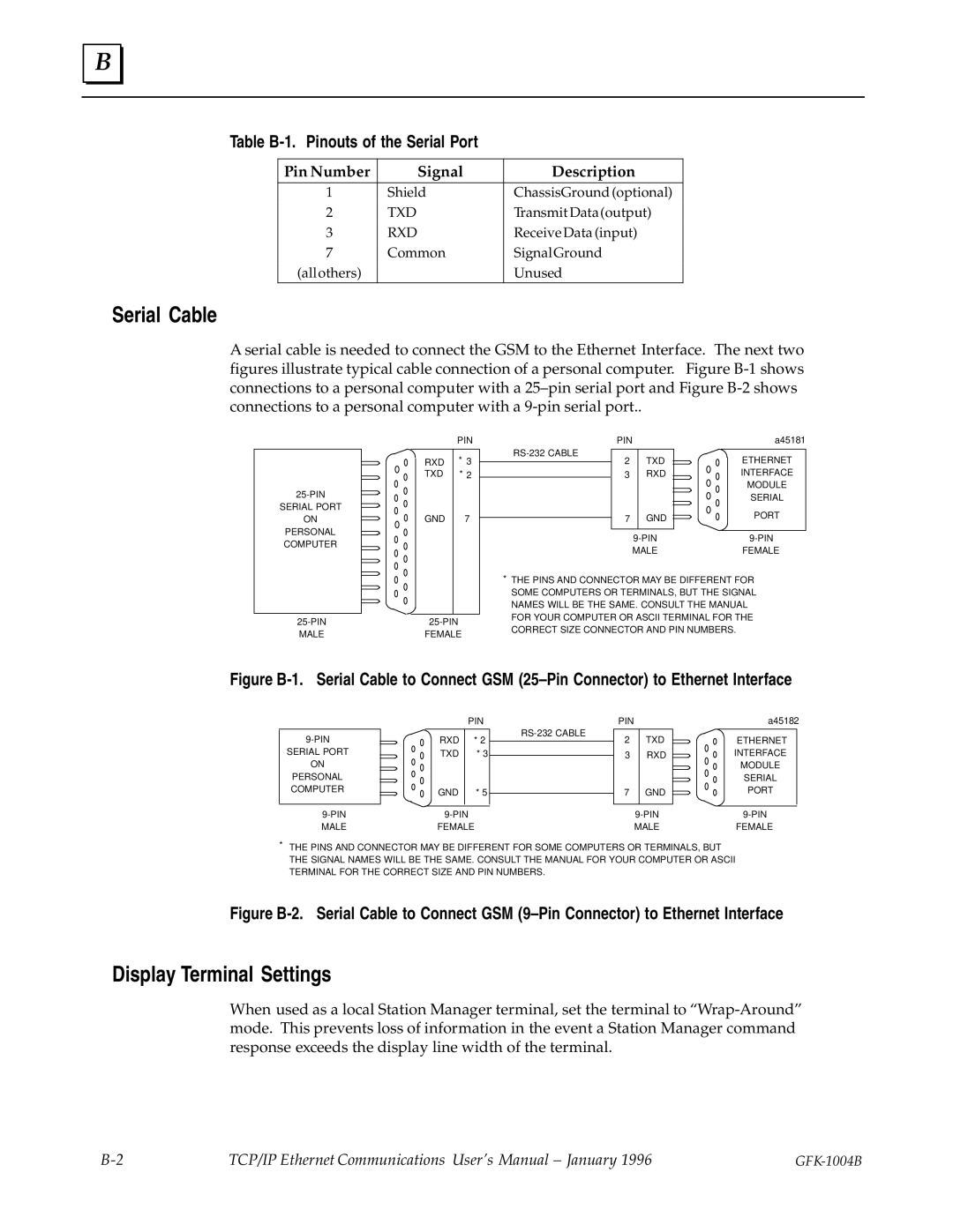
A serial cable is needed to connect the GSM to the Ethernet Interface. The next two figures illustrate typical cable connection of a personal computer. Figure
SERIAL PORT
ON
PERSONAL COMPUTER
| PIN |
RXD | * 3 |
TXD | * 2 |
GND | 7 |
PIN
2TXD
3RXD
7 GND
a45181
ETHERNET INTERFACE MODULE SERIAL
PORT
FEMALE
*THE PINS AND CONNECTOR MAY BE DIFFERENT FOR SOME COMPUTERS OR TERMINALS, BUT THE SIGNAL NAMES WILL BE THE SAME. CONSULT THE MANUAL FOR YOUR COMPUTER OR ASCII TERMINAL FOR THE CORRECT SIZE CONNECTOR AND PIN NUMBERS.
Figure B-1. Serial Cable to Connect GSM (25±Pin Connector) to Ethernet Interface
SERIAL PORT
ON
PERSONAL COMPUTER
|
| PIN |
| RXD | * 2 |
| ||
| TXD | * 3 |
| GND | * 5 |
|
|
|
FEMALE
PIN
2TXD
3RXD
7 GND
a45182
ETHERNET INTERFACE MODULE SERIAL PORT
FEMALE
*THE PINS AND CONNECTOR MAY BE DIFFERENT FOR SOME COMPUTERS OR TERMINALS, BUT THE SIGNAL NAMES WILL BE THE SAME. CONSULT THE MANUAL FOR YOUR COMPUTER OR ASCII TERMINAL FOR THE CORRECT SIZE AND PIN NUMBERS.
Figure B-2. Serial Cable to Connect GSM (9±Pin Connector) to Ethernet Interface
Display Terminal Settings
When used as a local Station Manager terminal, set the terminal to
TCP/IP Ethernet Communications User's Manual ± January 1996 |
|