6 |
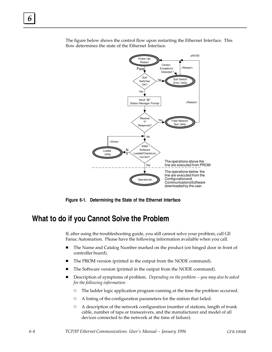
The figure below shows the control flow upon restarting the Ethernet Interface. This flow determines the state of the Ethernet Interface.
Power Up/ |
|
Restart | Certain |
| |
Pass | Exceptions |
| Detected |
a45163
<Restart>
Soft
No Soft Switch
Switches
OK?
Yes
Entry Utility
Issue º@º
Station Manager Prompt
<Restart>
Receive | Yes | Field Network | |
ºFº | |||
| Test Utility | ||
Response? |
| ||
|
|
|
| No |
<Done> |
|
|
|
| RAM |
Loader | N | Software |
Utility | o | Loaded/Checksum |
|
| Correct? |
Yes
Operational
The operations above the line are executed from PROM
The operations below the line are executed from the Configurationand CommunicationsSoftware downloaded by the user.
Figure 6-1. Determining the State of the Ethernet Interface
What to do if you Cannot Solve the Problem
If, after using the troubleshooting guide, you still cannot solve your problem, call GE Fanuc Automation. Please have the following information available when you call.
HThe Name and Catalog Number marked on the product (on hinged door in front of controller board).
HThe PROM version (printed in the output from the NODE command).
HThe Software version (printed in the output from the NODE command).
HDescription of symptoms of problem. Depending on the problem
h The ladder logic application program running at the time the problem occurred. h A listing of the configuration parameters for the station that failed.
h A description of the network configuration (number of stations, length of trunk cable, number of taps or transceivers, and the manufacturer and model of all devices connected to the network at the time of failure).
TCP/IP Ethernet Communications User's Manual ± January 1996 |
|