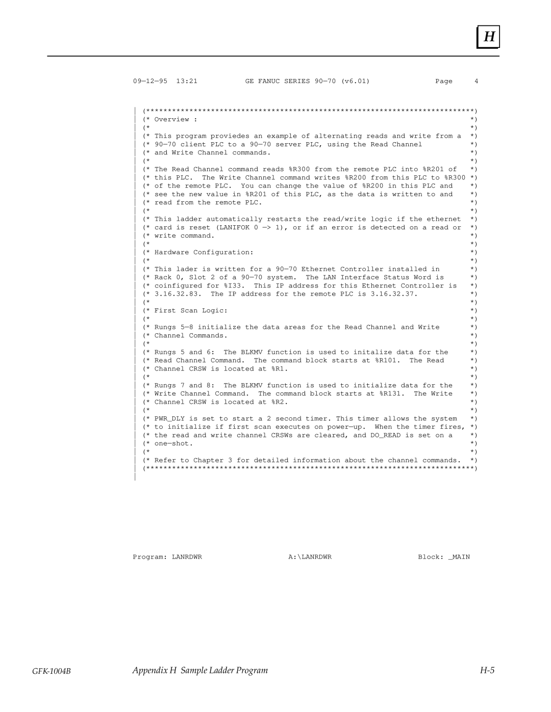
H |
09Ð12Ð95 13:21GE FANUC SERIES 90Ð70 (v6.01)Page 4
(****************************************************************************)
(* Overview : | *) |
(* | *) |
(* This program proviedes an example of alternating reads and write from a | *) |
(* 90Ð70 client PLC to a 90Ð70 server PLC, using the Read Channel | *) |
(* and Write Channel commands. | *) |
(* | *) |
(* The Read Channel command reads %R300 from the remote PLC into %R201 of | *) |
(* this PLC. The Write Channel command writes %R200 from this PLC to %R300 *)
(* of the remote PLC. You can change the value of %R200 in this PLC and | *) | |||
(* see the new value in %R201 of this PLC, as the data is written to and | *) | |||
(* read from the remote PLC. |
| *) | ||
(* |
|
|
| *) |
(* This ladder automatically restarts the read/write logic if the ethernet | *) | |||
(* card is reset (LANIFOK 0 Ð> 1), or if an error is detected on a read or | *) | |||
(* write command. |
|
|
| *) |
(* |
|
|
| *) |
(* Hardware Configuration: |
|
| *) | |
(* |
|
|
| *) |
(* This lader is written for a 90Ð70 Ethernet Controller installed in | *) | |||
(* Rack 0, Slot 2 of a 90Ð70 system. The LAN Interface Status Word is | *) | |||
(* coinfigured for %I33. | This IP address for this Ethernet Controller is | *) | ||
(* 3.16.32.83. The IP address for the remote PLC is 3.16.32.37. | *) | |||
(* |
|
|
| *) |
(* First Scan Logic: |
|
| *) | |
(* |
|
|
| *) |
(* Rungs 5Ð8 initialize the data areas for the Read Channel and Write | *) | |||
(* Channel Commands. |
|
| *) | |
(* |
|
|
| *) |
(* Rungs 5 and 6: | The BLKMV function is used to initalize data for the | *) | ||
(* Read Channel Command. | The command block starts at %R101. | The Read | *) | |
(* Channel CRSW is located at %R1. |
| *) | ||
(* |
|
|
| *) |
(* Rungs 7 and 8: | The BLKMV function is used to initialize data for the | *) | ||
(* Write Channel Command. | The command block starts at %R131. | The Write | *) | |
(* Channel CRSW is located at %R2. |
| *) | ||
(* |
|
|
| *) |
(* PWR_DLY is set to start a 2 second timer. This timer allows the system | *) | |||
(* to initialize if first scan executes on powerÐup. When the timer fires, *)
(* | the read and write channel CRSWs are cleared, and DO_READ is set on a | *) | |
(* | oneÐshot. | *) | |
(* |
| *) | |
(* Refer to Chapter 3 for detailed information about the channel commands. *) (****************************************************************************)
Program: LANRDWR | A:\LANRDWR | Block: _MAIN |
Appendix H Sample Ladder Program |
