2 |
Press firmly to lock the board in place, but do not force the board.
Note
The Ethernet Controller board will not operate properly if there are empty slots to the left of the slot you select.
5.Connect the free end of the safety wire (18 inch long green wire attached to the Ethernet Controller board) to the ground lug at the side of the Series
Warning
The ground wire must be securely fastened to the chassis of the Series
6.Connect the transceiver cable into the
7.Set the CPU Run/Stop switch to STOP.
8.Continue with Procedure 2: Verifying Ethernet Interface
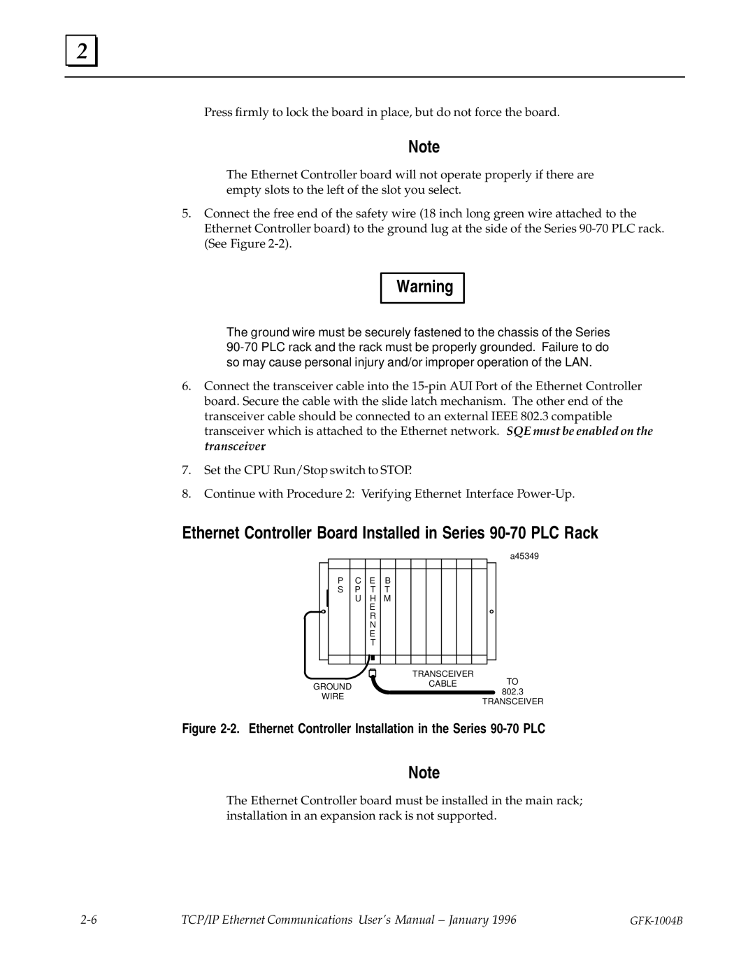
Ethernet Controller Board Installed in Series 90-70 PLC Rack
a45349
|
|
|
|
|
|
|
|
|
|
|
|
|
|
|
|
|
|
|
|
|
|
|
|
|
|
|
|
|
|
|
|
|
|
| P | C | E | B |
|
|
|
|
|
|
| ||
|
|
| S | P | T | T |
|
|
|
|
|
|
| ||
|
|
|
| U | H | M |
|
|
|
|
|
|
| ||
|
|
|
|
| E |
|
|
|
|
|
|
|
| ||
|
|
|
|
| R |
|
|
|
|
|
|
|
| ||
|
|
|
|
| N |
|
|
|
|
|
|
|
| ||
|
|
|
|
| E |
|
|
|
|
|
|
|
| ||
|
|
|
|
| T |
|
|
|
|
|
|
|
| ||
|
|
|
|
|
|
|
|
|
|
|
|
|
|
|
|
|
|
|
|
|
|
|
|
|
|
|
|
|
|
|
|
TRANSCEIVER
GROUNDCABLETO 802.3
WIRE
TRANSCEIVER
Figure 2-2. Ethernet Controller Installation in the Series 90-70 PLC
Note
The Ethernet Controller board must be installed in the main rack; installation in an expansion rack is not supported.
TCP/IP Ethernet Communications User's Manual ± January 1996 |