UDC Universal Digital Controller Product Manual
51-52-25-55D
Honeywell West Spring Street Freeport, Illinois
Revision D April
Contacts
Abstract
References
World Wide Web
Symbol Definitions
Symbol Definition
Table of Contents
205
Configuration Prompt Definitions
147
Operation
243
219
233
271
Figures
DC330X-EE-XXX-X2, DC330X-AA-XXX-X2
Tables
154
246
Xii UDC 3300 Controller Product Manual
Introduction
Pharmaceuticals, and testing and environmental work
Configurable parameters
Offered in a 1/4 DIN size controller
UDC 3300 Controller Product Manual
Operator Interface Displays and Indicators
Operator Interface
Function of keys
Loop 1/2
ToBEGIN
Key
SPn
OTI
UDC 3300 Controller Product Manual
Topic See
Overview
Introduction What’s in this section?
Normal Mode
Specifications
Stray Rejection Common Mode
Design
Solid State Relays One or Two
Current Output Isolated
Electromechanical Relays One or Two
Open Collector Outputs One or Two
RS422/485 Ascii RS422/485 Modbus
Power Consumption Power Inrush Current Weight
Dmcs
RTU
Voltage Vdc Voltage Vac 90 to 240 Vac 24 Vac Frequency Hz
Environmental and Operating Conditions
Mechanical Shock
Model Number Interpretation
Model number
Mounting
Physical considerations Overall dimensions
Dimensions
Step Procedure for Mounting the Controller Action
Refer to -3 and follow the procedure in -2 to mount
Mounting procedure
Controller
Electrical Noise Precautions
Wiring
Control/alarm circuit wiring
Electrical considerations
Permissible Wiring Bundling Bundle No Wire Functions
Shows which wire functions should be bundled together
Permissible wire bundling
Identify your wiring requirements
Wiring Requirements
Using the information contained in the model number, select
Wiring the controller
Controller accordingly
Wiring Diagrams
Due to the voltage drop caused by the in-rush current
Line voltage wiring
Controller 4 mm2
Except 0-10 Volts
Input #1/Input #2 connections
Thermocouple MV or Volts
Volts Milliamps
5V Connections MA Connections
Two Hlai replace second Llai connections
High Level Analog Input Connections See Below
22 + 23 +
Time proportional output
L2/N Power
Alarm Relay #1 Load
Electromechanical Relay Output-Model DC330X-EE-XXX
Alarm Relay #1 Load AC Load
Alarm Relay #2 Load
Relay Load Power
AC Load
10 10-amp Solid State Relay Output-Model DC330X-SS-XX
Time Proportional Simplex
Controller Load L2/N
Output or Alarm Load
Current output/ universal output connections
Ohms
Relay #1
16 +
Output Type Current
Mechanically linked To motor
Position proportional output connections
Calibration
Connect shield to ground At one end only
1000 Ω
Auxiliary output connections
Auxiliary Load
Digital inputs connections
TX-/RX
Full duplex wiring
Master L2/N
Do not mix half
Resistor
Master
120 Ohm
Configure
Diode here to reduce
Zero VAL = Span VAL =
+16 26 + 250 ohm Resistor
Voltage at transmitter
Lists the Control Relay contact information
Control and Alarm Relay Contact Information
Lists the Alarm Relay contact information
Topic
Continuous background tests that are being performed
Introduction
Prompts
TOT Rate * x = 0 to
Configuration Prompts
Diagram prompt hierarchy
Input
Parameter explanations or definitions
How To Get Started
Configuration record sheet
Configuration Tips
Configuration Tips
Configuration Procedure Step Operation
Configuration Procedure
Introduction Procedure
Press
SET UP Lower Display
Step Operation
Function prompts
Loop 1 Tuning Parameters Set Up Group
Factory Setting
Function Prompt
Function Name
Selections or Range of Setting
Disabl Enable
Function Selections or Name Range of Setting
Loop 2 Tuning Parameters Set Up Group Cascade or Two Loops
Tuning Loop 2 Group Function
Setpoint rate
SP Ramp, SP Rate, or SP Programming Set Up Group
Lists all the function prompts in the SP Ramp Set Up group
Function prompts Function Prompt
SEG3RATE SEG4 SP SEG4TIME
Recycles Soak DEV Prog END State Keyreset Hotstart
SEG1RATE SEG2 SP SEG2TIME
SEG5RATE SEG6 SP SEG6TIME
Accutune Set Up Group
Accutune Group Function Prompts
Lists the function prompts in the Accutune Set Up group
Factory Refer Setting
Function Selections or
Algorithm Group Function Prompts
Algorithm Data Set Up Group
Introduction Function prompts
Math K Calc HI Calc LO ALG1 INA ALG1 INB ALG1 INC
INP ALG1
None
PCO SEL PCT CO ATM Pres ALG1BIAS INP ALG2
ALG2 INB
Factory Setting Refer
ALG2 INA
ALG2 INC
Totalize Xxxxxxx TOT Scal TOT SEC Rset ? TOT Rate
OUT ALG
Output Algorithm Parameters Set Up Group
Output Algorithm Group Function Prompts
OUT2 ALG Rlystate
IN1 Type XMITTER1
Input 1 Parameters Set Up Group
Input 1 Group Function Prompts Selections or
Analytic IN1 HI IN1 LO Ratio
BURNOUT1
Bias IN1
Filter
None Down Nofs
Input 2 Parameters Set Up Group
Input 3 Parameters Set Up Group
Input 3 Group Function Selections or Range of Setting
12 Control Group Function Prompts Selections or
Loop 1 Control Parameters Set Up Group
Process
Dropoff Deadband OUT Hyst Failmode Failsafe Swfail
OUT Rate
PCT/M UP PCT/M DN
MAN OUT Auto OUT
INP
Loop 2 Control Parameters Set Up Group
13 Control 2 Group Function Prompts
Dropoff Deadband Failmode Failsafe
OUT Rate PCT/M UP PCT/M DN
OUTHiLIM OUTLoLIM HiLIM I LoLIM
Options Group Function Prompts
Options Set Up Group
Prompts will not appear
AUX OUT CUR OUT2
+RUN
DIG1 COM DIG2 COM
+DISAT
None Disabl
Shedenab Shedtime Parity Baud
Communications Set Up Group
15 Communications Group Function Prompts
Duplex
Fsafe To MAN To LSP To CSP Percnt ENG
Last To LSP Percnt Disabl
Alarms Set Up Group
A1S1 VAL A1S2 VAL A2S1 VAL A2S2 VAL
A1S1 EV
A1S1TYPE A1S2TYPE A2S1TYPE A2S2TYPE
A1S1 H L
A1S2 H L
A2S2 H L
A2S1 H L
A2S1 EV
A2S2 EV AL Hyst ALM OUT1 Block
Decimal
Display Parameters Set Up Group
Display Group Function Prompts
DECIMAL2
Calibration Group
Calibration data
Maintenance Group Function Prompts
Maintenance Set Up Group
Others, to keep track of maintenance needs
Elapsed Time Timer
Status test data
Counter Number of Counts Password Reset Type
Status Group
Disabl None
Configuration Record Sheet
Keep a record
Function Value or Prompt Selection
Value or Selection Factory Setting
Group Prompt
Expanded Model DC330E-XX-XXX
Value or Selection
Control CONTROL2 Options
UDC 3300 Process Controller Product Manual
Configuration Prompt Definitions
Upper Display Range of Setting Or Selection
Introduction Set this group last Tuning group prompts
Tuning Group Prompt Definitions Lower Display
Parameter Definition
Lower Display Prompt
Rset MIN Rset RPM MAN Rset PROPBD2 Gain
Security Lockout Auto MAN SP SEL RUN Hold
None Calib + Conf + View MAX Disabl Enable
Configure Until ALL Configuration is Complete
Gain PV band over which each Value Gain applies
Loop 2 Tuning Group Prompt Lower Display
Loop 2 Tuning Parameters Set Up Group
Introduction Tuning 2 group prompts
Setpoint Ramp/Rate Group Definitions Lower Display Prompt
Setpoint Ramp/Rate/Programming Set Up Group
Introduction SP Ramp/Rate/ Programming group prompts
Final SP SP Rate
EU/HR UP EU/HR DN EU/HRUP2
Or Selection
EU/HRDN2 SP Prog
Introduction Accutune group prompts
Accutune Group Definitions Lower Display Prompt
Disabl Tune TUN+PV SP+PV
Demand Tuning Plus PV Adaptive TUNE- Same
Setpoint Tuning Plus PV Adaptive TUNE- Same
Accutune for Loop
KPG SP CHAN2
Criteria CRITERA2
Runing None Outlim Idfail Abort LOW PV
AT Error AT ERR
Read Only
Introduction Algorithm group prompts
Algorithm Group Definitions Lower Display Prompt
PID a PID B
3PSTEP Loop 2LOOPS Cascad
ALG
Pidloops
PID a PID B PD+MR Disabl HI SEL LO SEL
None AVG
Timer Period Start Disp
KEY ALARM2 TI REM Time
Input High Select with Ratio and BIAS- This
Relhum
Summer with Ratio and BIAS- The following
Multiplier with Square ROOT- The following
Carb B Carb C Carb D FCC DEW PT Oxygen
Math K Calc HI Calc LO
For Example
Disabled
INP LP1OUT LP2OUT AL1 AL2 None Disabl Online
FFWDM2
Lower Display Upper Display Prompt Range of Setting
FWR2
Mult
PCT H2 ALG2BIAS
Where
Summary of Flow Values At Values Conditions
Flow Sfcm
X1 Input Value X Axis
8SEG CH1
X0 Input Value X Axis
X2 Input Value X Axis
Segment Characterizer #2- a second eight
X0 VALU2
Example of Eight Segment Characterizer
Read only
Totalize Xxxxxxx TOT Scal TOT SEC Rset ?
Unlock Lock YES
Second Minute Hour DAY ML/DAY
Time Currnt Positn Time D
Introduction Output algorithm group prompts
Output Algorithm Group Definitions Lower Display Prompt
CUR D CUR TI TI CUR
Other prompts affected 4-20 RNG
OUT2 ALG Rlystate RLY Type
Input 1 group prompts Lower Display Prompt
Upper Display Parameter Range of Setting Definition
Bias, filter, burnout, and emissivity
Input 1 Group Definitions
Conductivity
Xmitter Analytic
ORP
Resistivity
IN1 LO Ratio Bias IN1 Filter Burnout
EMISSIV1
Input 2 Group Definitions
Slidewire
Introduction Input 2 group prompts Lower Display Prompt
IN2 Type
IN3 Type
Introduction Input 3 group prompts Lower Display Prompt
Input 3 Group Definitions
XMITTER2 IN3 HI IN3 LO Ratio Bias IN3 Filter
Input
Introduction Control group prompts Lower Display Prompt
PV Source PID Sets
Input Algorithm
Three
PID Sets SW Value LSP’S
2PV SW 2SP SW Gain S
Setpoint Select
RSP SRC Autobias SP Track
Manual LSP RSP
Control Output DIRECTION- Select direct or reverse acting
For Three Position Step Control Only
SP HiLIM
OUT Rate PCT/M UP
Dropoff
Failsafe Mode
OUTLoLIM Hi LIM Lo LIM
OUT Hyst Failmode Failsafe Swfail
RPM MIN
PBorGAIN
PB PCT Gain
PV 2 SRC
Introduction Control 2 group prompts
11 Control 2 Group Definitions Lower Display Prompt
Input Input Algorithm Force MA PID Sets
Only TWO Three
RSP SRC Autobias Sptrack
Hi LIM Lo LIM
Revrse Disabl Enable
OUT HiLIM OUT LoLIM
128 UDC 3300 Process Controller Product Manual
Options Group Definitions
Selection with desired scaling
Option group prompts Lower Display Prompt
No Auxiliary Output
AUX OUT
DEV Output LSP AL1 AL2 PV2 OUTPT2 SP L2
No Digital Input Selections
CB OUT2
None To MAN To LSP To 2SP To 3SP To DIR
PV 2IN PV 3IN Rerun To RUN
Stop MAN FS
TRACK1 TRACK2
To RSP RST FB
Any Digital Input Selection Plus RUN Setpoint
DIG DIG 1 COM
DIG DIG2 COM
Digital Input 2 Selections
ComSTATE Com Addr ComADDR2
Introduction Communications group prompts
13 Communications Group Definitions Lower Display Prompt
Shed Enab
Even Parity
Shedtime Parity Baud Duplex
Wsfloat
To LSP To CSP
Last Toauto Fsafe
Shed SP
Percnt ENG
138 UDC 3300 Process Controller Product Manual
A1S1 VAL A1S2 VAL A2S1 VAL
Introduction Alarms group prompts
14 Alarms Group Definitions Lower Display Prompt
A1S1TYPE
No Alarm Input
Alarm on Manual Mode Loop 1 Note
Event on SP Programming Event OFF SP Programming
High LOW Begin END
High Alarm LOW Alarm
A1S2TYPE A2S1TYPE A2S2TYPE
Beginning of Segment END of Segment
How to configure alarm to turn on and off with HealthWatch
AL Hyst ALM OUT1 Block
Decimal DECIMAL2 Temp Unit PWR Freq Ratio
Introduction Display group prompts Lower Display Prompt
Display Group Definitions
Calibration Data
Maintenance Group
Maintenance Group Definitions
Input Calibration in this manual for complete information
TIME1
Gsoak Sootng DIGIN1 DIGIN2 MAN2
Status Test Data
Failure. Refer to the Troubleshooting in this manual for
COUNTS1 COUNTER2 COUNTS2 COUNTER3 COUNTS3 Password RES Type
Complete information
Operation
How to Power Up the Controller
Keys Procedure for Testing the Displays and Keys Press
Key Pressed Lower Display
Entering a Security Code
Introduction Security code numbers Procedure
Step Procedure for Entering a Security Code Press Action
Until you see
Decimal point position
Monitoring Your Controller
Operator interface
Annunciators
Automatic Mode MAN-Manual Mode
Degrees Fahrenheit Degrees Celsius
BIA Tune OFF Tune RUN
Viewing the operating parameters
Lower Display Key Parameter
Diagnostic error messages
Error Messages Description
Enter the local
Start-up Procedure
Start-up procedure is given in Table
Setpoint
Operating Modes
Available modes Mode definitions
Operating Mode Definitions
Remote Setpoint Manual Cascade Automatic Cascade
What happens when you change modes
Changing Operating Modes Mode Change
Selecting manual or automatic mode
SP 2SP 3SP RSP CSP
Position proportional backup mode
Setpoints
Introduction Selecting the local setpoint source
Changing local setpoint 1, 2, or
Hold
Enabling or disabling the remote setpoint
Setpoint selection indication
Configuration Operation
Setpoint Ramp Rate
Single Setpoint Ramp
Configuring the setpoint ramp Procedure
14 Procedure for Configuring a Setpoint Ramp Step Operation
SP Ramp
UDC 3300 Controller Product Manual 165
Running the setpoint ramp Procedure
15 Procedure for Running a Setpoint Ramp Step Operation
UDC 3300 Controller Product Manual 167
Using Two Sets of Tuning Constants
Introduction Select two sets or gain scheduling
Rate Rset
Set switchover value
Set tuning constant values for each set
RSET2
= 1 or
Alarm Setpoints
Introduction Procedure for displaying the alarm setpoints
21 Control Loop Selections Input Input Algorithm
Two Loops of Control Overview
Introduction Selections
Loop
Loop 1 and Loop 2 of a dual loop controller
Functional overview
Internal cascade
Override rules
Is a block diagram of the Hi/Lo Override Selector
Two-loop restrictions
Model DC330E-KE-5XX
25 Procedure for Selecting Output Algorithm Step Operation
Configuring Two Loops of Control
24 Procedure for Selecting 2-loop Algorithm Step Operation
Select the output algorithm for each loop
Procedure in -26 shows you how select the 2 loop algorithm
Select control parameters for each loop
27 Procedure for Selecting Tuning Parameters Step Operation
Procedure in -27 shows you how select the Tuning Parameters
Select tuning parameters for each group
28 Digital Display Indication-Two Loops
Indicator
Monitoring Two Loops of Control
Loop Indication
Operating modes and setpoint source Keyboard operation
Operating Two Loops of Control
Loop operation
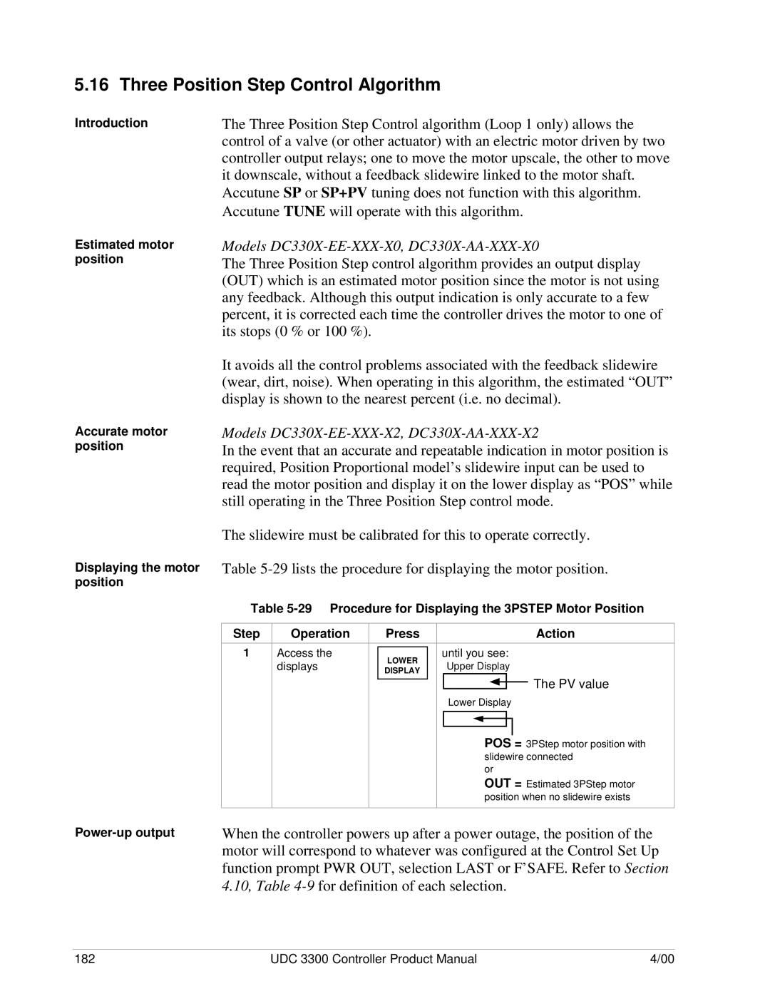
Three Position Step Control algorithm Loop 1 only allows
Power-up output
Three Position Step Control Algorithm
Accutune Tune will operate with this algorithm
Input Math Algorithms
Introduction Input algorithm selections
Xn Value Yn Value
Segment characterization Totalizer function
Alarm on totalizer value Totalizer reset via digital input
30 Digital Input Option Action on Contact Closure
Digital Input Option Remote Switching
Introduction Action on closure
Stop MAN FS
Timer AM STA
To RUN
TRACK1 TRACK2
Display Indication
Means that the parameter is configured and the action
Will occur when the digital input is active
Action on contact closure
Digital Inputs 1 and 2 Combination Action Example
State DI #1 Open DI #1 Closed
Auto/Manual Station
Introduction Function
Up Group Function Prompts
Refer to -33 and set up the controller in the order shown
Description Configuration
Press To Enter Remarks
Value or Selection Algorithm
Step Press
Up Group Function Prompts Press To Enter Remarks
Options
Introduction How it works Configuration
Fuzzy Overshoot Suppression
Accutune
Rules
How Tune demand tuning works
34 is a list of rules for Accutune
34 Accutune Rules and Regulations Applicable Rule
Switch to Automatic mode by pressing the MANUAL/AUTO key
Starting Tune demand tuning
35 Procedure for Starting Tune Demand Tuning Step Action
Using Tune at start-up for duplex heat/cool
Setpoint changes
Step Action
Using SP tuning at start-up
37 Procedure for Using SP Tuning at Start-up
MANUAL/AUTO
Using SP tuning at start-up for duplex heat/cool
SP tuning after start-up Aborting SP tuning
Error prompt accessing procedure
Values are entered and used until retuning occurs again
Retuning
Key to return to manual mode. This will
39 Accutune* Error Prompt Definitions Action to Take
39 lists the Accutune error prompts and their definitions
Error prompt Upper Display Prompt
Introduction Features
Carbon Potential
UDC
Diagram
Carbon Potential Control
HealthWatch maintenance alarms
When the desired threshold is reached
See .18 Maintenance for details on using the various
HealthWatch
What’s in this section
What is programming? Review program data and configuration
Fill out the worksheet
Program Contents
UDC 3300 Controller Product Manual 207
Ramp unit
Drawing a Ramp/Soak Profile
Ramp/Soak Profile example
Program Record Sheet
Segment Value Prompt
Alarms on the setpoint program Prompt hierarchy
Make sure SP Ramp and SP Rate are disabled first
Setpoint Program Data Entry Procedure Press Result
Entering the Setpoint Program Data
Prompt Hierarchy and Available Selections
Value or Selection use or
SEG8 SP SEG8TIME SEG9RAMP SEG9RATE SG10 SP SG10TIME
Definition Value or Selection use or
SEG2 SP SEG2TIME SEG3RAMP SEG3RATE
SG11RAMP SG11RATE SG12 SP SG12TIME
Local Setpoint Value
Run/Monitor the Program
Introduction Run/monitor functions
Set the Local Setpoint
# RA
Power-up state
Viewing the number of cycles left in the program End Program
Procedures for Changing a Running Setpoint Program Function
Result/Action
218 UDC 3300 Controller Product Manual
Input Calibration
Introduction What’s in this section
RTD
Minimum and Maximum Range Values
Honeywell Radiamatic Type RH Type RI
IEC Alpha=0.00385 Ohms Ohms low Linear
Calibration steps
Disconnect the field wiring
Preliminary Information
Equipment needed
Equipment Needed Type of Input
Input
Input #1, #2, or #3 Set Up Wiring
Thermocouple inputs using an ice bath
Thermocouple inputs using a precision resistor
Wiring Connections for RTD
RTD inputs
Radiamatic, millivolts, or volts except 0 to 10 volts inputs
Volts only Input
Wiring Connections for 0 to 10 Volt Inputs
To 10 volt inputs
250Ω Resistor Assy
Input 3-Wire terminals as shown below
To 20 mA inputs
Copper Leads To 20 mA Source
Make sure you have Lockout set to NONE. See Section
Input #1, #2, or #3 Calibration Procedure
Input #1, #2, or #3 Calibration Procedure
From initial value to final 100 % value
Step Description
If… Then…
Restoring Factory Calibration Step Operation
How to restore it Procedure
Restoring Factory Calibration
Action/Result
Step Operation Press
Output Calibration
Equipment needed Calibrator connections
Current Proportional Output Calibration
Between 0 mA and 21 mA
Make sure Lockout in the Tuning Set Up group is set to
NONE. See Configuration
Rules for auto mode vs manual mode Displayed values
Procedure
Procedure for calibrating the Position Proportional output
Lockout in Tuning Set Up group is set to NONE. See Section
These prompts only appear when position OUT ALG is
Do MAN
Do Auto or
Do Auto
Lower Display SET UP
Desired span value
Any other values between 0 mA and 21 mA
Set Up Wiring Procedure for Auxiliary Output Step Action
Auxiliary Output Calibration
Auxiliary Output Calibration Procedure Press Action
Value between 0
242 UDC 3300 Controller Product Manual
Troubleshooting / Service
Hardware and software related problems
Installation related problems
Application related problems
Troubleshooting Aids
Error Message Prompts
Number
Status
Power-up Tests Upper Display
Power-up Tests
What happens at power-up
Test failures
RAM Test Conf Test CAL Test Fact CRC
Introduction How to check the status tests
Status Tests
Fail
Status Tests
RAM Test Conf CAL Test Fact CRC
Pass
EE Fail
Background Tests
Introduction Background tests
INP1FAIL INP2FAIL INP3FAIL
PV = INP1 + INP1 Bias
Lower Display Reason for Failure How to Correct the Problem
INP1 RNG INP2 RNG INP3 RNG PV Limit RV Limit
RV = INP2 X Ratio + Bias
Troubleshooting procedure indicated to correct the problem
Controller Failure Symptoms
Compare your symptoms with those shown in -7 and refer to
Reacting
Troubleshooting Power Failure Symptoms Step What to do
Troubleshooting Procedures
Equipment needed Procedure #1
How to do it
Procedure #2
Procedure #3
Procedure #4
Procedure #5
13 explains how to troubleshoot Alarm Relay Output failure
Procedure #6
14 explains how to troubleshoot a Keyboard failure
Procedure #7
15 explains how to troubleshoot a Communications failure
Procedure #8
Parts Replacement Procedures
Introduction Equipment needed
How to remove the chassis
16 How to Remove the Chassis Step Action
Refer to -2 and follow the procedure listed in Table
How to replace the display/keyboard assembly
How to remove the printed wiring boards from the chassis
18 Printed Wiring Board Removal from Chassis Step Action
MCU
Printed wiring board identification
On Digital Input and MCU/Output boards
Prom
20 Power Input Board Replacement Procedure Step Action
19 Second Input Board Replacement Procedure Step Action
Power input board
2nd input board
21 Digital Input Board Replacement Procedure Step Action
Digital input board
Aux.Out/ communications board
MCU/output board
23 MCU/Output Board Replacement Procedure Step Action
Current Output-P/N Relay Output-P/N
Maintenance
Cleaning
Exploded View
There is a list of parts not shown in Table
Key Part Number
Parts identification
Parts not shown
Description Quantity
Appendix a Manual Tuning
Manual Tuning Procedure for Simplex Control
Time, Position, or Current Proportional Simplex Control
Manual Tuning Formulas Units
To Reduce Overshoot
PB or Gain
Two Sets of Tuning Parameters for Single Output Operation
Tuning function prompts for HEAT/COOL are
Rsetmin or Rsetrpm RSET2MIN or RSETRPM2
Index
278 UDC 3300 Controller Product Manual
Y, Z
280 UDC 3300 Controller Product Manual
Page
Sensing and Control