Page
Page
PCL 5 Printer LanguageTechnical Reference Manual
HP Part No First Edition October
Page
Printing History
Trademark Credits
Experienced Users
Inside This Manual
What You Can Learn From This Manual
Non-technical Users
Application notes can be obtained through the HP Forum on
Chapter Summaries
Software packages, refer to HP’s Software Application Notes
Brief description of each chapter is provided below
Fonts
Macros
PCL Rectangular Area Fill Graphics
Viii
Configuration and Status Group
Related Documentation
PCL 5 Comparison Guide
Contents
Print Environment
Decipoints Columns & Rows
Horizontal Cursor Positioning Decipoints Command
Cursor Positioning Units
BS Backspace HT Horizontal Tab
Contents-4
10-4
MSL Symbol Index Example 10-14
10-2
10-5
First Code UI 11-30 Last Code / Number of Characters UI
11-29
Text Height UI 11-29
Height Extended UB 11-31 Cap Height UI
Macro Control Example
16-6
Symbol Set Response 16-18
Contents-8
16-8
17-9
17-2
17-3
Parameter Formats 17-10
19-8
19-3
19-4
Enlarging or Reducing a Picture 19-8
21-6
21-2
21-3
21-10
ExampleUsing the FI Command 23-54
ExampleUsing the DR Command 23-41
ExampleUsing theDV Command 23-49
ExampleUsing the FN Command 23-57
Error
HMI
Contents-14
HP PCL
PCL Printer Language Architecture
2Introduction to HP PCL
Control Codes
What are Printer Commands?
PCL Commands
4Introduction to HP PCL
HP-GL/2 Commands
PJL Commands
Two-character escape sequences have the following form
Syntax of Escape Sequences
Two-Character Escape Sequences
6Introduction to HP PCL
Parameterized Escape Sequences
Parameterized Character a character from
?&l1O and ?&l2A
Case l for clarity
Character and a termination character. This escape sequence
8Introduction to HP PCL
Introduction
Logical
2The
More information
Printed Dots
HP LaserJet printer
Current top margin position
PCL Coordinate System
PCL coordinate system is defined as shown in Figure
Is changed
Decipoints
Units of the PCL Coordinate System
PCL Units
Columns & Rows
Not affected by the PCL print direction
Used. The default HP-GL/2 picture frame is the current top
HP-GL/2 Picture Frame
6The
At 300 DPI double for 600 DPI
Printable Area
Portrait Logical Page & Printable Area Boundaries
Landscape Logical Page & Printable Area Boundaries
8The
Is positioned using the Left Registration command
Printable Area Character Cell Positioning
10The
Describes the Factory Default Environment, the User Default
Group of all of the printer’s current feature settings
Maintains four print environments the Factory Default
Printer commands select other settings
Factory Default Print Environment Features
Factory Default Environment
Default settings for specific printers, refer to
PCL Context
Picture Frame Height
Factory Default Print Environment Features PCL Context
Line Termination Picture Frame Width
Pattern Rotation Macro ID
Current Location Type Current Location Unit
4The Print Environment
Scale Mode
Factory Default Print Environment Features HP-GL/2 Context
Symbol Set Polygon Buffer Font Spacing Polygon Mode Pitch
User Default Environment
6The Print Environment
PCL Context HP-GL/2 Context
Modified Print Environment
Items Not Included in Modified Print Environment
Printers, refer to the PCL 5 Comparison Guide
Command and the EC%-12345Xcommand Universal Exit
Resetting the Print Environment
Printer Reset
Critical. Refer to -1 for an example of their usage
Cold Reset
10The Print Environment
Structure of a Typical Job
Preamble
Printer Reset Command
2PCL Job Control Commands
Universal Exit Language Command
? % 1 2 3 4 5
Example
Number of Copies Command
4PCL Job Control Commands
? & l #
Are bound along the width of the physical page see Figure
Simplex/Duplex Print Command
Feature print in simplex mode front side of sheet only
Be a concern if available user memory is critical
Long-Edge Binding Mode
Short-Edge Binding Mode
= The number of decipoints 1/720 inch
Left Offset Registration Command
? & l # U
Negative values cause it to move right refer to -4
? & l # Z
Top Offset Registration Command
8PCL Job Control Commands
Short-Edge Binding Mode Offsets
?&a#G
Duplex Page Side Selection Command
10PCL Job Control Commands
?&a1G
? & l 1 T
Job Separation Command
Separation, the command is ignored
Separation will be performed
12PCL Job Control Commands
Output Bin Selection Command
Dual output bin feature, it is ignored
? & l # G = 1 Upper Output Bin Lower Rear Output Bin
# =Number of units-per-inch
Unit of Measure Command
? & u # D
Information
Over 7200=0.3332 4801-3600over 3600=0.3336
Relative error when mapped to 3600
14PCL Job Control Commands
Dpi print resolution
Units moves the cursor 1.5 inches, whether printed at 300 or
16PCL Job Control Commands
If a number of consecutive pages within a job have the same
Control commands and data are associated with each
Command
Only once for that group of pages. Remember, once a PCL
? & l # a
Size Command
2Page Control Commands
Paper
LaserJet+, or the LaserJet 500+ printers
? & l3A
To feed paper from the manual feed slot, send
4Page Control Commands
? & l # H
?&l2H
# = 0 Portrait Landscape Reverse Portrait Reverse Landscape
Logical Page Orientation Command
? & l # O
HP-GL/2 State Variables
Orientation With Default Print Direction
8Page Control Commands
Command ?&l#O or the HP-GL/2 RO command
Print Direction Command
Print Direction does not default HMI
? & a # P
10Page Control Commands
Changing Print Direction on a
Text Area
12Page Control Commands
Text Area Within
# = Column number
Left Margin Command
? & a # L
To set the left margin to column 5, send
? & a # M
Right Margin Command
?&a45M 14Page Control Commands
To set the right margin to column 45, send
Clear Horizontal Margins Command
? & l # E
Top Margin Command
?&l4E 16Page Control Commands
First line of the logical page is line
Margin Cursor Positioning
? & l # F
Text Length Command
?&l6ØF 18Page Control Commands
Perforation Skip Command
? & l # L
? & k # H
Horizontal Motion Index HMI Command
20Page Control Commands
Horizontal Motion Index HMI Command
? & l # C
Vertical Motion Index VMI Command
22Page Control Commands
# = number of 1/48 inch increments between rows
Common VMI Settings
?&l5.45C 5.45 = 7.5/66 x
Line Spacing Command
Cursor Positioning
Absolute vs. Relative Cursor Positioning
2Cursor Positioning
Cursor Positioning Units
4Cursor Positioning
Width of a column is defined by the current HMI
Horizontal Cursor Positioning Columns Command
? & a # C = Number of Columns
# = Number of Decipoints 1/720 inch
Horizontal Cursor Positioning Decipoints Command
? & a # H
6Cursor Positioning
= Number of PCL Units
Horizontal Cursor Positioning PCL Units Command
? * p #
Logical
SP Space
Horizontal Cursor Positioning Control Codes
CR Carriage Return
Inch, the HMI is rounded to the nearest 1/300 inch
BS Backspace
HT Horizontal Tab
= Number of Rows
Vertical Cursor Positioning Rows Command
? & a # R
Position on
= Number of Decipoints 1/720 inch
Vertical Cursor Positioning Decipoints Command
? & a #
# = Number of PCL Units
Vertical Cursor Positioning PCL Units Command
? * p # Y
12Cursor Positioning
LF Line Feed
Half-Line Feed Command
Vertical Cursor Positioning Control Codes
FF Form Feed
# = 0- CR=CR LF=LF FF=FF
Line Termination Command
? & k # G
14Cursor Positioning
Push/Pop Cursor Position Command
? & f # S
16Cursor Positioning
Fonts
Font Sources
2Fonts
Symbol Set
Printers. See for more information
Spacing
4Fonts
Pitch
Height
6Fonts
Stroke Weight
Style
Typeface Family
Typeface
Orientation
8Fonts
Bitmap Fonts and Scalable Typefaces
11 Bitmap Character
12 Scalable Character
Internal Fonts
Special Effects
Fonts
PCL Font Selection
2PCL Font Selection
Font Selection Priority
Font Priority Considerations
Priority of Locations
Font, followed by a 300 dpi bitmapped soft font
Typeface Family Courier
Font Select Table
MediumÍ
4PCL Font Selection
Primary and Secondary Fonts
Font Resolution
Characteristics be sent to ensure that the correct font is
Selection method. However, HP recommends that all
6PCL Font Selection
Symbol Set Command
EC ID Secondary Symbol Set Command
Example
Typical Symbol Set Values
Symbol Set Name Symbol Set ID
ISO 6ASCII
Bit ISO Symbol Sets
8PCL Font Selection
Spacing Command
Pitch Command
10PCL Font Selection
Vendor
Select table See Font Selection by ID Command later in this
Courier is very close to 60% of an Em, and 30 = 1 ÷ 0.64 ÷
Chapter for more information
Height Command
12PCL Font Selection
ID Command later in this chapter for more information
To specify a height of 12 points for the primary font, send
Value Font Styles
Style Command
Common Font Styles
14PCL Font Selection
Available for the next selection
255 to 0-32767. This expansion allows for additional styles
Described under Style MSB in Chapter
To specify an upright style for the primary font, send
Stroke Weight Command
Stroke Weights
To specify a bold stroke weight for the primary font, send
Instead
Comparison Guide, for future typeface selection
Typeface Family Command
Comparison Guide for typeface values
18PCL Font Selection
ECs4101T
Sample Typeface Values
FamilyValue Typeface Family
ECs0T
20PCL Font Selection
Font Selection Examples
Bitmap, Fixed-Spaced Font
Scalable, Proportional-Spaced Font
Summary of Font Selection by Characteristic
Eliminated before the selection process begins
Thinner stroke weight is selected
24PCL Font Selection
Summary of Font Selection by Characteristic
26PCL Font Selection
Font Selectionby ID Command
Characteristic is not changed
HP-GL/2 Font Selection
Select Default Font Command
Characteristic is not affected by the default font command
Examples
Transparent Print Data Command
28PCL Font Selection
Aligned or be the same thickness
Underline Command
EC & d @ Disable underline
30PCL Font Selection
Font Management
Downloading Soft Fonts
2Font Management
Deleting Fonts
Whenever the printer’s power is turned off
Temporary vs. Permanent Fonts
Appropriate printer User’s Manual for specifics
Font ID Command
4Font Management
To remove only those soft fonts that are temporary, send
Font Control Command
To remove all soft fonts from user memory, send
To delete the soft font with an ID of 1, send
6Font Management
Font Management Example
Designate the permanent soft font as primary
Font Selection and Unbound Fonts
Unbound Scalable Fonts
Bound and Unbound Fonts
8Font Management
Complement number
Symbol Collections
Various collections
10Font Management
Character Complement Numbers
Character Requirements Number
Symbol Set Mapping Table
Final Font Selection
12Font Management
Roman-8 Symbol Index Mapping
MSL Index Unicode Index Character Code Decimal Hexadecimal
Printing a Character
14Font Management
User-Defined Symbol Sets
Symbol Set Control EC*c#S
Symbol Set ID code = # * 32 + ID
Symbol Set ID Code Command
# = Symbol Set ID Code decimal
10-2User-Defined Symbol Sets
Page
User-Defined Symbol Set Defintion Format
Define Symbol Set
Data format for the user-defined symbol set is shown
10-4User-Defined Symbol Sets
ULI
Header Size UI
Font Header Field Data Type Notation
Unsigned Long Integer
10-6User-Defined Symbol Sets
Encoded Symbol Set Designator UI
Symbol Set Type UB
Format UB
Specifies the first character code in the set
First Code UI
Last Code UI
10-8User-Defined Symbol Sets
Ascii not required
001 Unicode Symbol Index
Ascii required such as ISO 6 Ascii
French
MSL
10-10User-Defined Symbol Sets
Bit Field Designated Use Value Hex Meaning
Symbol Map Array of UI
Symbol Set Control Command
10-12User-Defined Symbol Sets
Symbol Map Data
User-Defined Symbol Set Examples
Unicode Symbol Index Example
MSL Symbol Index Example
10-14User-Defined Symbol Sets
Symbol Map Data
10-16User-Defined Symbol Sets
Soft Font Creation
HP LaserJet printer PCL bitmap, Intellifont scalable,
Font ID Command Font Header
Font Classifications
11-2Soft Font Creation
This manual, for information on how to obtain this document
Intellifont Scalable Fonts
Coordinate System
Bitmap Fonts
Fonts to match the paper’s physical coordinate system
TrueType Scalable Fonts
Agfa Design Window
Font Header Format
Font Header Command
Default Range
This chapter
Format 0 Font Header for PCL Bitmapped Fonts
Byte 15 MSB LSB
15 MSB LSB
Format 20 Font Header for Resolution-Specified
Bitmapped
11-8Soft Font Creation
Font Name Resolution Copyright optional
Format 10 Font Header for Intellifont Bound Scalable
Font Number 11-10Soft Font Creation
Format 10 Font Header for Intellifont Bound
Global Intellifont Data Size
Or Threshold Global Italic Angle
Font Name Scale Factor Resolution
Master Underline Thickness
Character Complement
Format 15 Font Header for TrueType Scalable Fonts
Global Intellifont Data
Copyright optional Reserved Checksum
Byte 15 MSB LSB0
11-14Soft Font Creation
Data Types
Font Header Field Data Type Notation
Font Type UB
Font Descriptor Size UI
Header Format UB
Header Format Values
Value Posture StyleWord partial sum
Style MSB UI
Refer to for more information
Alternate Italic
Appearance Width
Multiply by 4 for StyleWord partial sum
Cell Height UI
Baseline Position UI
Cell Width UI
11-18Soft Font Creation
Orientation UB
Character Cell Bitmap
Bitmap Font Unsupported values invalidate font creation
Symbol Set UI
Spacing B
Scalable Font set to zero
Pitch UI
11-22Soft Font Creation
Height UI
XHeight UI
Width Type SB
Stroke Weight SB
14 Stroke Weight Values
Style LSB UB
Semi Bold Demi Bold
Typeface UB
Current Usage
Extra Bold Black Extra Black Ultra Black
Current Vendor Number Values
Value Vendor
Vendor Version
Previous Usage
17 Typeface Family Value Previous
18 Previous Vendor Number Values
Value Serif Style
Serif Style UB
Serif Style Values
Quality UB
Placement SB
21 Bitmap Font Placement Values
19 Serif Style Values
Text Height UI
Underline Position Distance SB
Underline Thickness UB
Text Width UI
Font Type First Code../..Last Code
Last Code / Number of Characters UI
Pitch Extended UB
11-30Soft Font Creation
Scalable Font Set Pitch Extended field to zero
Height Extended UB
Cap Height UI
Agfa
Font Number ULI
Initial HexValue Vendor Name
Bigelow && Holmes
This field is ignored by the printer for bitmap fonts
Resolution UI
Font Name ASC16
Necessary for TrueType fonts
Master Underline Thickness Height UI
Scale Factor UI
Master Underline Position SI
Font Scaling Technology UB
Global Italic Angle SI
Variety UB
Or Threshold UI
Global Intellifont Data Size UI
11-36Soft Font Creation
MSL Symbol Index
Unicode Symbol Index
27 MSL Symbol Index Character Complement Bits
Bit Value
11-38Soft Font Creation
28 Unicode Symbol Index Character Complement Bits
Unicode
Segmented Font Data Format
Checksum
Copyright
Segment
Value Mnemonic Data Segment
Segment Identifier UI
30 Segmented Font Data
11-40Soft Font Creation
Data segments with an unrecognized identifier are ignored
Segment Size UI
Formats of Data Segments
GI Global Intellifont Data Reserved for future use
PF PS-Compatible Font Name Reserved for future use
Checksum
If Intellifont Face Data Reserved for future use
11-42Soft Font Creation
Font Header Examples
Bitmap Example
Pitch Extended Height Extended Cap Height
Intellifont Scalable Example
First Code Last Code
56.02% of Em
Design Height
29.63% Em Default HMI
Reference in Design
Points
11-46Soft Font Creation
Font Header Examples
Character Definitions
11-48Soft Font Creation
=character code
Character Code Command
Symbol index value
Character Definition Command
11-50Soft Font Creation
Character descriptors
Character Descriptor Formats
Character Descriptor and Data Format for PCL Bitmap Fonts
34 Character Descriptors/Data Continuation Block
11-52Soft Font Creation
Format UB
Format Continuation non-zero Raster Character Data in bytes
Class UB
Continuation B
Descriptor Size UB
11-54Soft Font Creation
Class 1 Bitmap Data
Class 2 Compressed Bitmap Data
Class 2 Character Data
Top Offset SI
Orientation UB
Left Offset SI
Portrait Landscape Reverse portrait Reverse landscape
Delta X SI
Character Width UI
Character Height UI
Character Data
Portrait Character Example
11-58Soft Font Creation
Landscape Character Example
11-60Soft Font Creation
Reserved Checksum2
41 Intellifont Scalable Contour Data Format
Contour Tree Data XY Coordinate Data
LaserJet Family Raster
11-62Soft Font Creation
Contour Data Size UI
Class 3 -Intellifont Scalable Character Contour Data
Class 4 Intellifont Scalable Compound Character Data
Metric Data Offset SI
XY Data Offset SI
Character Intellifont Data Offset SI
Contour Tree Offset SI
Metric Data
Number of Components UB
Character Descriptor and Data Format for TrueType Fonts
Compound Character Escapement SI
Component List
11-66Soft Font Creation
Format Continuation Descriptor Size Class
Character Data Size Desc Glyph ID
Desc Size Beginning of TrueType Glyph Data
Intellifont Scalable
11-68Soft Font Creation
TrueType Glyph Data
Character Data Size UI
Glyph ID UI
Checksum UB
52 Character Format, Continuation, and Descriptor
Character Definition Examples
Bitmap Portrait Character Example
11-70Soft Font Creation
Decimal Equivalent
53 Portrait Character Data Example
Dot Row
11-72Soft Font Creation
Bitmap Landscape Character Example
54 Character Format, Continuation and Descriptor
55 Landscape Character Data Example
11-74Soft Font Creation
HP-GL/2 commands are not supported within macros on all
When printing letters, for example, which include a company
Printer, initiates the command sequence to print
Concern, a possible solution might be an HP custom macro
12-2Macros
Macro Creation
MacroDefinition End of the macro data definition
Macro Invocation
12-4Macros
Temporary / Permanent Macros
HP-GL/2 Context
# =Macro ID number
Deleting Macros
Macro ID
To establish a macro ID number of 5, send
Macro Control
Execute another macro two levels of nesting are allowed
ROM-Based Macros
12-8Macros
Macro Control Example
Macros
PCL Print Model
Source Image
Source Transparency Mode
Pattern
Destination Image
Pattern Transparency Mode
Opaque and Transparency Modes
Effect of Transparency Modes on Images
13-4The PCL Print Model
Command Sequence
Operation Comments
13-6The PCL Print Model
Source Transparency Mode Command
End of Page Data
Pattern Transparency Mode Command
Were opaque white rules erase black rules regardless
Selecting Cross-Hatch
Pattern ID Area Fill ID Command
Default No pattern Range
Selecting Shaded patterns Patterns
Area Fill Graphics. It is duplicated here for convenience
Shading Patterns
13-10The PCL Print Model
Cross-Hatch Patterns
Pattern E #T and the Pattern ID E
Select Current Pattern Command
Shading pattern Cross-hatch pattern User-defined pattern
13-12The PCL Print Model
User-Defined Pattern Graphics
User-Defined Pattern Implementation
13-14The PCL Print Model
Pattern Reference Point
Tile point is moved for the next fill area
Moving Pattern Reference Point for Pattern Filling
Resolution-Specified User-Defined Pattern Header
User-Defined Pattern Command
User-Defined Pattern Header 300 dpi resolution
Pixel Encoding Byte
Format Byte
Continuation Byte
Reserved Byte
Master X Resolution UI
Master Y Resolution UI
Height in Pixels Bytes 4
User-defined Pattern Example
13-20The PCL Print Model
Send the pattern header and binary data
FF FF
Set Pattern Reference Point Command
13-22The PCL Print Model
Pattern Control Command
13-24The PCL Print Model
Rectangular Area Fill Procedure
14-1,cross-hatch pattern -2, or user-defined
Decipoints=E #H, or PCL Units=E *c#A
14-2PCL Rectangular Area Fill Graphics
Measure Command in Chapter
Horizontal Rectangle Size Decipoints Command
Horizontal Rectangle Size PCL Units Command
Measure is set to 600 units-per-inch
14-4PCL Rectangular Area Fill Graphics
Vertical Rectangle Size Decipoints Command
Vertical Rectangle Size PCL Units Command
Selecting User-Defined patterns1
Selecting Shaded Patterns
# = Thru 2 = 1- 2% shade Pattern #1
14-6PCL Rectangular Area Fill Graphics
Shading Patterns
14-8PCL Rectangular Area Fill Graphics
Fill Rectangular Area Command
14-10PCL Rectangular Area Fill Graphics
Pattern Transparency for Rectangular Area Fill
Effect of Transparency Modes on Rectangular Areas
14-12PCL Rectangular Area Fill Graphics
Solid Fill Black/White
Rectangular Area Fill Examples
Pre-defined Pattern Examples
Shaded Fill
14-14PCL Rectangular Area Fill Graphics
Shaded Fill Example
Cross-hatch Fill
14-16PCL Rectangular Area Fill Graphics
Patterned Fill Example
User-Defined Pattern Fill Example
14-18PCL Rectangular Area Fill Graphics
Raster Graphics
Raster Area
15-2Raster Graphics
Page
Raster Graphics Command Sequence
15-4Raster Graphics
To the printable area
Test, font printout, or power cycle
Raster Compression are all true modes. Once specified,
15-6Raster Graphics
Raster Graphics Resolution Command
Requires 540,000 bits
Raster Graphics Expansion at 300 dpi
Raster Graphics Expansion at 600 dpi
Orientation Default Graphics Margin
Raster Graphics Presentation Mode Command
Default Range Raster
Portrait Logical page left bound Reverse portrait Landscape
Raster Graphics Presentation Mode for Portrait Orientation
Landscape Dots in from the logical Top bound Reverse
Raster Graphics Presentation Mode for Landscape Orientation
15-10Raster Graphics
Raster Height Command
Cursor
Maximum Raster Height
15-12Raster Graphics
Raster Width Command
Start Raster Graphics Command
15-14Raster Graphics
Raster Y Offset Command
Method nor the left raster graphics margin
Run-length Encoding Method
Set Compression Method Command
Unencoded Method
15-16Raster Graphics
Tagged Image File Format Encoding Method
Repeated Pattern Values
Literal Pattern Values
No Operation Value
Examples Run-length and Tiff Compression
Byte Number Bits
15-20Raster Graphics
Command byte1 to 8 Replacement bytes
Delta Row Compression Method
Command Byte
Seed Row
15-22Raster Graphics
Next delta row is applied to a zeroed seed row
Printing a Zeroed Row Setting the Seed Row to Zero
Repeating a Row
Previous row to be replicated
15-24Raster Graphics
Example Delta Row Compression
Byte Row
Adaptive Compression Method
Value Compression Operation
15-26Raster Graphics
Empty Row
Duplicate Row
Adaptive Compression Operation Hints
15-28Raster Graphics
Transfer Raster Data Command
End Raster Graphics Command
15-30Raster Graphics
11 Example of Raster Graphic Image Data
Command Data
Raster Graphics Example
Dot Row Byte
15-32Raster Graphics
11Example of Raster Graphic Image Data
15-34Raster Graphics
Status Readback
Description Data
Memory Status Request
Memory Status Request Example
16-2Status Readback
PCL Info Memory TOTAL=100000 LARGEST=25000
Entity Status
Status response sent from printer to host
PCL
Example PCL Operation Command Comments
Entity Status Request Example
Info Fonts
Status Response
Ignore lines with keywords they do not recognize
Status Response Syntax
Value field
Two example status responses are shown below
Feed decimal 12 control codes. The Esc following
Example listings, CR, LF, and FF identify
Carriage Return decimal 13, Line Feed decimal 10, and Form
Control code decimal
Set Status Readback Location Type Command
16-8Status Readback
Location Type Unit
Set Status Readback Location Unit Command
Set Status Readback Location Unit Command
Inquire Status Readback Entity Command
16-10Status Readback
Entity Status Responses
Symbol set are described below
SELECT= SYMBOLSETS= LOCTYPE= LOCUNIT=
Font Response
16-12Status Readback
Bitmap Fonts
Scalable Fonts
Location Type 1 Currently Selected Font
Unbound Scalable Fonts
Soft Fonts
LOCUNIT=1
16-14Status Readback
Font Extended Response
None
16-16Status Readback
Macros and returns an error ERROR=NONE
Macro Response
User-Defined Pattern Response
Macro status response might appear as shown below
Unit
Symbol Set Response
Symbol set response might appear as shown below
16-18Status Readback
Entity Error Codes
Invalid Entity Invalid Location None Internal Error
16-20Status Readback
Memory, an internal error is returned, as shown below
Given
Free Space Command
16-22Status Readback
Memory Status Response
Free Space status response returns two values
Memory Error Response
LARGEST=25000
Is processed and ejected from the paper path
Flush All Pages Command
All page data including the partial page will be processed
16-24Status Readback
Echo Command
Echo command followed by a Free Space command. The printer
16-26Status Readback
Echo command returns the following response
Echo Response
Status Readback Programming Hints
16-28Status Readback
17-1
Learning HP-GL/2
HP-GL/2 Commands and Syntax
HP-GL/2 Commands by Group 1
HP-GL/2 Commands by Group 2
HP-GL/2 Commands by Group 3
FN1
HP-GL/2 Commands by Group 4
FI1
SV1
HP-GL/2 Commands by Group 5
Understanding HP-GL/2 Syntax
TR1
Typical HP-GL/2 Command
Notations Used to Express Syntax
Omitting Optional Parameters
LT6,25,1
LT6,1
Parameter Formats
LT6
Page
PM1/PM2 forms of PM
Down until a PD command is received
PR, RA, RR, RT, and WG
17-12An Introduction to HP-GL/2 Vector Graphics
Using HP-GL/2 With Programming Languages
ExampleBASIC
ExampleC Programming Language
17-14An Introduction to HP-GL/2 Vector Graphics
HP-GL/2 Coordinate System
Coordinate System to Match the PCL System in Chapter
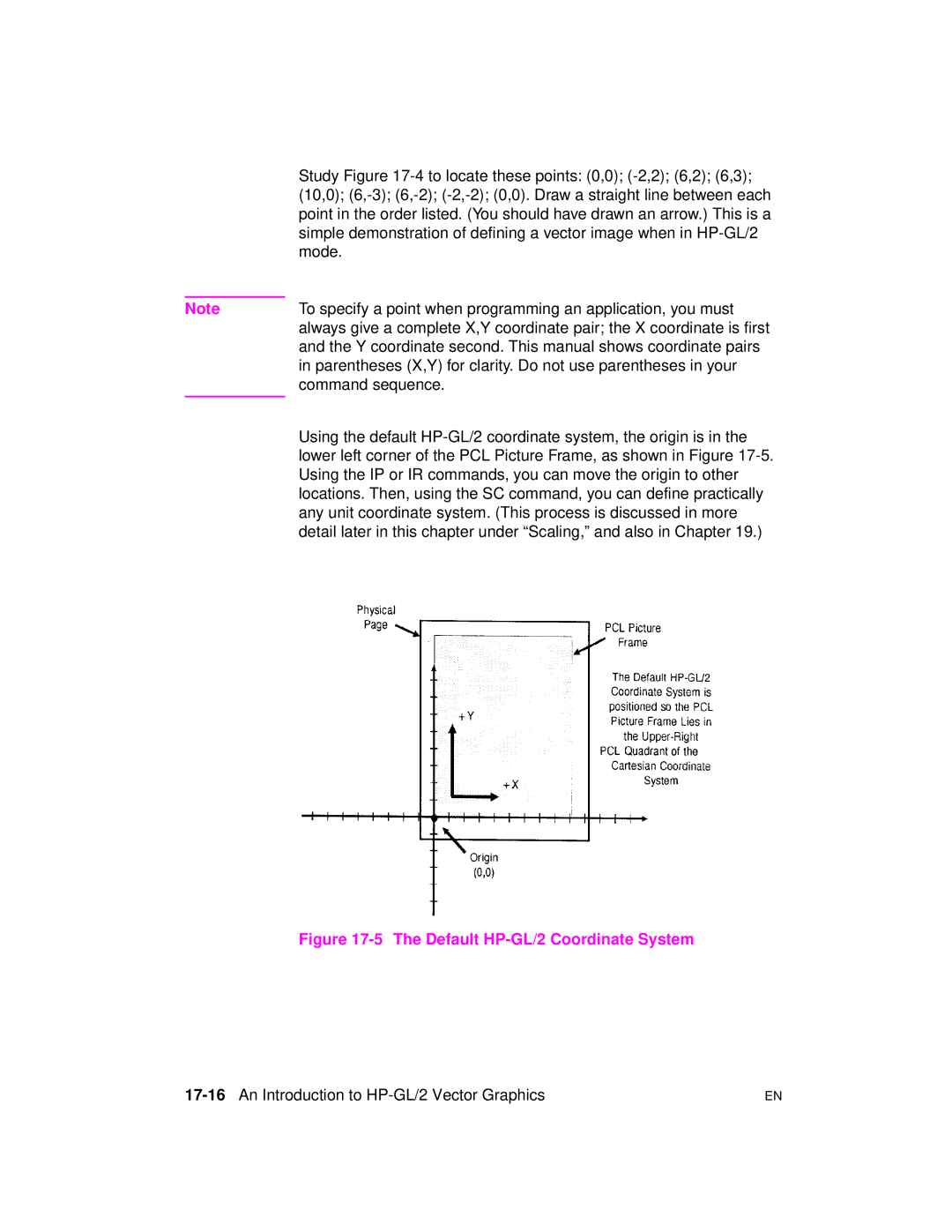
Parentheses X,Y for clarity. Do not use parentheses in your
Using the default HP-GL/2 coordinate system, the origin is
Mode
17-16An Introduction to HP-GL/2 Vector Graphics
Matches the PCL orientation. -7 shows how the RO
Command modifies the default HP-GL/2 orientation
HP-GL/2 & PCL Orientation Interactions
Change in PCL print direction has no effect on the HP-GL/2
Modifying HP-GL/2 Orientation on a Portrait
17-18An Introduction to HP-GL/2 Vector Graphics
Vector Graphics Limits
Printer’s printable limits, see Chapter
User-units
HP-GL/2 Units of Measure
Plotter Units
PlotterUnits EquivalentValue
Pen Status and Location
Pen Status
Commands That Include an Automatic Pen Down
Command Group
Pen Location
Scaling
17-24An Introduction to HP-GL/2 Vector Graphics
Absolute and Relative Pen Movement
Absolute Coordinates
Coordinates as the opposite corner
As absolute plotter units unless a PR Plot Relative command
SC command is in effect
Numbers and therefore transmit less data over the I/O
Picture Frame
Defining the Image AreaPCL Picture Frame
18-2The Picture Frame
Creating a Page Size-Independent Plot
18-4The Picture Frame
Enlarged or reduced to fit the PCL Picture Frame the amount
Size. See to specify an HP-GL/2 plot size
Typical HP-GL/2 PlotCommand Sequence
Example Creating and Using a PCL Picture Frame
18-6The Picture Frame
Current HP-GL/2 pen position
Width of the current logical
When the print direction is set to 0 degrees the default
Horizontal Picture Frame Size
Valid to 4 decimal places
Vertical Picture Frame Size Decipoints
Print direction is
Logical page and the default top margin
Set Picture Frame Anchor Point
Anchor point or the picture frame
Range To 32767 valid to 4 decimal places
Default
HP-GL/2 Plot Horizontal Size
HP-GL/2 Plot Vertical Size
18-12The Picture Frame
EC%1B
Enter HP-GL/2 Mode
EC % # B
EC%0A
Enter PCL Mode
Mapped to
18-14The Picture Frame
Default Settings
Example Creating a Simple Drawing
18-16The Picture Frame
INSP1
Borders
PU50,50CI25
Circle with a radius that is 25%
18-18The Picture Frame
Configuration and Status Group
To their default conditions
Configuration and Status Group Commands
Command Summary
19-2The Configuration and Status Group
Environment and how it is affected by the reset command
Establishing Default Conditions
Language mode, you should establish default conditions at
DF command is not as powerful as the in command.
Scaling Points P1 and P2
Using the Scale Command
19-4The Configuration and Status Group
User-Unit Scaling with Default P1 and P2
19-6The Configuration and Status Group
Arc that falls within the effective window is printed
New P1 and P2 User-Unit Scaling with Negative Values
Enlarging or Reducing a Picture
Using Scaling Effectively
19-8The Configuration and Status Group
Example Changing the Size of a Drawing
EC%0B
19-10The Configuration and Status Group
Drawing Equal-Size Pictures on a
Example Drawing Equal-Size Pictures on a
Enter HP-GL/2 mode, using
Reset the printer to complete the job
EC&l1O Select landscape orientation
19-12The Configuration and Status Group
Creating Mirror-Images
Send a reset to end the job and eject
Enter HP-GL/2 mode
Enter the PCL mode
Example Creating a Mirror-Image
PA1,2PD1,4,3,4,3,7,2,7
19-14The Configuration and Status Group
Subroutine
Subroutine that prints the arrow figure on the next
Example Adapting the HP-GL/2 Coordinate System
Adapting the HP-GL/2 Coordinate System to
Match the PCL System
19-16The Configuration and Status Group
EC%1A
Enter the PCL mode with the CAP at
Four Types of Line Segments
Windowing Setting Up Soft-Clip Limits
19-18The Configuration and Status Group
Type From Last Point To New Point
Function Command Default Condition
DF, Default Values
Default Conditions
CO, Comment
SB0
19-20The Configuration and Status Group
LO1
Related commands
IN, Initialize
PD, PU
Affected Commands Group
DF, RO, IP
WU, PW
Parameter Format Functional Range Default
IP, Input P1 and P2
11 Commands Affected by P1/P2
19-24The Configuration and Status Group
IW, Input Window RO, Rotate Coordinate System SC, Scale
Related Commands Group
IR, Input Relative P1 and P2
IR, Input Relative P1 and P2
Functional Parameter Format Range Default
19-26The Configuration and Status Group
10Example P1 and P2 command
13 Commands Affected by P1/P2
19-28The Configuration and Status Group
Current 30 to 2 30
IW, Input Window
IP, Input P1 and P2
15 Example The IW Command
19-30The Configuration and Status Group
Lbthis is AN Example
IW@
13Example IW command
19-32The Configuration and Status Group
PG, Advance Full
Same position on the next
RO, Rotate Coordinate System
RO command
19-34The Configuration and Status Group
Angle of Rotation
Scaling points P1 and P2 rotate with the coordinate system
Positive angle of rotation
Location to reflect the new orientation
Upper-right corners of the picture frame
15Using the RO Command Without Using the IP
19-36The Configuration and Status Group
16Using IP after the RO Command
19-38The Configuration and Status Group
Input Relative P1 and P2 IW, Input Window
RP, Replot
Source defaults the HP-GL/2 pen position
Illustration, see Number of Copies Command in Chapter
SC, Scale
Real 30 to 2 30 No default
19-40The Configuration and Status Group
Parameter Format
Scaling Form
For Scaling Types 0
Scaling Form Type Description
Syntax
19-42The Configuration and Status Group
18Isotropic Scaling
Scaling Form Type Syntax
19-44The Configuration and Status Group
For Scaling Type
SC, Scale
23 Possible Error Conditions for SC
Condition Printer Response
Pen location through two
Vector Group Commands
Bezier Relative Draws a bezier curve using
Absolute points
20-2The Vector Group
Drawing Lines
Relative points
EC%ØA
Example Drawing Lines
EC%ØB
%ØB
Drawing Circles
Example Drawing Circles
%ØA
Example Drawing Arcs
To enable printing
Drawing Arcs
20-6The Vector Group
Draw the arc for 180 in a negative angle
Rotation
Drawing arcs 2
20-8The Vector Group
Drawing Bezier Curves
Example Drawing Bezier Curves
AA, Arc Absolute
Current units 30 to 2 30 No default
Sweep angle Clamped real 32768 to No default Chord angle
20-10The Vector Group
Enable printing
SP1 Select pen number 1. Even though there is no
20-12The Vector Group
LA, Line Attributes LT, Line Type PW, Pen Width
Current 30 to 2 30 No default
AR, Arc Relative
Circle that would be drawn if the arc was 360 degrees
Example Using Arc Relative to Draw Arcs
20-14The Vector Group
Line Type PW, Pen Width
AT, Absolute Arc Three Point
20-16The Vector Group
10 Example Using the AT Command
PU3300,800 PD3500,800
PU650,450 PD1000,450
Pen down, and draw a line to
Down, and draw a line to 3500,800
BR, Bezier Relative
LT, Line Type PW,Pen Width
Specify relative plotting and pen down
12 Example Using the BR Command Bezier Relative
Prpd
BR0,3048,4572,0
LT, Line Type PW, Pen Width
BZ, Bezier Absolute AR, Arc Relative
CI, Circle RT, Relative Arc Three Point LA, Line Attributes
20-22The Vector Group
14 Example Using the BZ Command Bezier Absolute
BZ, Bezier Absolute
Specify relative plotting and pen
BR, Bezier Relative AR, Arc Relative
20-24The Vector Group
CI, Circle
16 Example Effects of Chord Angle on Circle Smoothness
20-26The Vector Group
Send a reset to end the job
LTCI5
20-28The Vector Group
RT, Relative Arc Three Point LA, Line Attributes
EW, Edge Wedge
WG, Fill Wedge SC, Scale
PA, Plot Absolute
20-30The Vector Group
PR, Plot Relative PD, Pen Down PU, Pen Up Line Attributes
Line Type PW, Pen Width SM, Symbol Mode
PD, Pen Down
20 Example Using the Pen Down Command
20-32The Vector Group
Polyline Encoded Plot Relative PU, Pen Up Line Attributes
LT, Line Type PW, Pen Width SM, Symbol Mode
Coordinate
Flag Character ‘’, ‘’, ‘’, ‘=’, or ‘7’
Command. Also, you must use a semicolon to terminate PE
PE, Polyline Encoded
20-34The Vector Group
Flag Meaning Description
Pen number Integer Number of fractional binary bits 26 to
PE while in polygon mode, the Select Pen command is ignored
Value Format Range
20-36The Vector Group
Fraction adjustment. If you are
Or base 32 equivalent 7-bit mode
24 Procedure to encode a number
You are encoding fractional data otherwise, begin with step
If x ≥ = 2 ×
= round
10,525
Else = 2 × absx +
Range Type Non-terminator Terminator
26 Procedure for determining base range
25 Terminator and non-terminator characters
Next order digit 64ths place 63 + 8 = CHR$
20-40The Vector Group
When converting and encoding data, note the following
Example Using the PE Command
Specify the next coordinate in absolute mode PA or PE=
MOD 64 = n.AND.63. The number is logically ANDd with
‘‘260 Lprint ’’
20-42The Vector Group
PD, Pen Down Plot Relative PU, Pen Up Line Attributes
20-44The Vector Group
Increments Current 30 to 2 30 No default Units
PR, Plot Relative
28 Example Using the PR Command
Coordinate
20-46The Vector Group
Pen Up
PD, Pen Down Polyline Encoded Line Attributes
Last unmatched coordinate
20-48The Vector Group
RT, Relative Arc Three Point
Chord angle Clamped real
31 Example Using the RT Command Relative Arc Three Point
Plu from the beginning of the arc
Current location, place the pen
Away, with an ending point 0,-1500
20-50The Vector Group
From the starting point of the arc
20-52The Vector Group
Polygon Group Commands
Polygon Group
21-2The Polygon Group
Using the Polygon Buffer
Mnemonic Command Name
Example Drawing Rectangles
?%0B Enter HP-GL/2 mode Initialize HP-GL/2 mode SP1
Drawing Rectangles
Pen to print HP-GL/2 images
Example Filled Rectangles
21-4The Polygon Group
Leaves its definition in the polygon buffer
Just drawn. Since the previous RR command
Draw an edge around the rectangle that was
1500,1000, you do not need to specify
Drawing Wedges
21-6The Polygon Group
PA2500,3500 Specify absolute plotting and move to location
Clarification
Example Drawing Wedges
Example Filling Wedges and Circles
21-8The Polygon Group
Hatching--parallel lines, with 75 plu
Wedge using the same center
PA2300,2500FT3, 75,45
Lines tilted at
Drawing Polygons
Drawing Subpolygons
PR, Plot Relative PU, Pen Up RT, Relative Arc Three Point
21-12The Polygon Group
Filling Polygons
Even/Odd Fill Method
Non-Zero Winding Fill Method
Filling Polygons Even/Odd Fill Method
21-14The Polygon Group
Drawing Circles in Polygon Mode
`Approximating Polygon Buffer Use
Counting the Points in a Polygon
Counting the Points in a Circle or Arc
21-16The Polygon Group
EA, Edge Rectangle Absolute
Any two diagonally opposite corners
Example Using EA to Draw Rectangles
21-18The Polygon Group
Lower left corner at 105,65
21-20The Polygon Group
10 Example Using the EP Command
EP, Edge Polygon
EA, Edge Rectangle Absolute
21-22The Polygon Group
Starting point of the rectangle. Increments are interpreted
Are restored
ER, Edge Rectangle Relative
Two diagonally opposite corners
12 Example Using ER to Draw Rectangles
21-24The Polygon Group
Opposite corner
Upper right corner
A point 40,-25 user-units away as
With the current pen location being one
21-26The Polygon Group
EW, Edge Wedge
17Anisotropic and Isotropic Scaling
21-28The Polygon Group
Radius -1000 sets the zero-degree
14 Example Using EW to Draw a Pie Chart
Angle of 180. The minus sign before
21-30The Polygon Group
To be filled
Even/odd fill algorithm default
FP, Fill Polygon
Non-zero winding fill algorithm
17 Example
Circle with a 500 plu radius and a 5 default
Exit polygon mode
Chord angle. Close the current polygon
Related Commands Group
Polygon Clamped Definition Integer
PM, Polygon Mode Command
PM0 or PM
21-34The Polygon Group
IN, Initialize AA, Arc Absolute
Polygon Mode Allowable Commands Group
DF, Default Values
Mode, earlier in this chapter for more details
PM1
21-36The Polygon Group
20 Example Using the PM Command
PM2
PM2FPEP
21-38The Polygon Group
RA, Fill Rectangle Absolute
Coordinates Current units 230to 230 No default
Command includes an automatic pen down. When the command
21-40The Polygon Group
22 Example Using the RA Command with Different Fill Types
Lower left corner and 800,1200 as
Related Commands Group
RR, Fill Rectangle Relative
21-42The Polygon Group
Example Using the RR Command with Different
24 Example Using the RR Command with Different Fill Types
21-44The Polygon Group
WG, Fill Wedge
26Fill Wedge with Scaling
21-46The Polygon Group
WG, Fill Wedge
26 Example Filling then Edging vs Edging then Filling Chart
21-48The Polygon Group
Following example illustrates this
When transparency mode TR command is opaque, filling then
Center point of the above circle is located at 0,0
27 Example
21-50The Polygon Group
Fpep
Epfp
EW,Edge Wedge SC, Scale
21-52The Polygon Group
Line and Fill Attribute Commands
Line and Fill Attributes Group
22-2The Line and Fill Attributes Group
Using Line Attributes and Types
Wedges
Commands Affectedby Line Types
Line Types Attribute
Using Fill Types
22-4The Line and Fill Attributes Group
Selecting a Pen and Changing Line Width
Fill Area Anchor Corner
22-6The Line and Fill Attributes Group
AC, Anchor Corner
Example Changing the Anchor Corner
RR1000,1000 Rectangle ER1000,1000 ?%0A Enter the PCL mode
PA3000,3000
22-8The Line and Fill Attributes Group
FT, Fill Type
Fill Type Description Option1 Option2
+X-axis to the -Y-axis
HP-GL/2
Referenced from the positive plotter-unit X-axis, as shown
22-10The Line and Fill Attributes Group
FT, Fill Type
HP-Defined Shading Patterns
22-12The Line and Fill Attributes Group
Example Using the FT Command
PCL Cross-Hatch Patterns
Same rectangle
Being the current pen location
Upper right corner 2500 plu to the right
22-14The Line and Fill Attributes Group
LA, Line Attributes
Attribute Kind Value Description
22-16The Line and Fill Attributes Group
Line Ends
Line Joins
12Five Line Joins
13Overlapping Line Ends without Line Join Selection
Miter Limit
14Miter Limit
LA1,4
Example Using the LA Command
PD3100,1900 Line to 3100,1900 ?%0A Enter the PCL mode
22-20The Line and Fill Attributes Group
Related Commands Group
LT, Line Type
LT99 Functional Parameter Format Range Default
Line type Clamped integer Solid line Restores previous
22-22The Line and Fill Attributes Group
LA,Line Attributes
11 Commands that Affect LT1 LT8
AC,Anchor Corner
12 Commands that Affect LT99
22-24The Line and Fill Attributes Group
Percentages
17Line Type Patterns and Pattern Percentages
22-26The Line and Fill Attributes Group
18Fixed and Adaptive Line Types
FT,Fill Type
AA,Arc Absolute
22-28The Line and Fill Attributes Group
PW, Pen Width
Width Clamped real 32768 to Dependent Pen Integer Black
14 Example Using the PW Command
22-30The Line and Fill Attributes Group
SV, Screened Vectors WU, Pen Width Unit Selection
RF, Raster Fill Definition
22-32The Line and Fill Attributes Group
White
Pen Number Represents a pixel in the pattern being defined
Indicates its color black or white
16 Example Creating and Printing a Fill Pattern
FT, Fill Type SV, Screened Vectors
22-34The Line and Fill Attributes Group
SM, Symbol Mode
22-36The Line and Fill Attributes Group
18 Example Using the Symbol Mode Command
SMZ
Related Commands Group
SP, Select Pen
22-38The Line and Fill Attributes Group
Screentype Clamped 2, 21 No screening solid Integer
WU, Pen Width Unit Selection TR, Transparency Mode
SV, Screened Vectors
Pattern Index Pen User-defined
Description Option1 Option2
Shaded Fill Shading Ignored
22-40The Line and Fill Attributes Group
23 Possible Error Conditions
FT, Fill Type PW, Pen Width RF, Raster Fill Definition
22-42The Line and Fill Attributes Group
TR, Transparency Mode
Parameter Format Functional Range Default Clamped integer
23Transparency Mode = OFF
Transparency mode is defaulted by the ?E Reset, IN, or DF
UL, User-Defined Line Type
22-44The Line and Fill Attributes Group
24 Example Using the UL Command
22-46The Line and Fill Attributes Group
26 Possible Error Conditions
WU, Pen Width Unit Selection
PW, Pen Width
22-48The Line and Fill Attributes Group
CP,Character Plot Moves the pen the specified
Character Group Commands
Rendered
23-2The Character Group
Printing Labels
Example Printing Labels
23-4The Character Group
Moving to the Carriage Return Point
Commands Updating Carriage Return Point to Current Location
Mnemonic Command Name1
Absolute Arc
Backspace Horizontal tab Line feed
Relative Arc
Control Code DecimalCode
Shift Out1
Shift In2 Space
Default Label Conditions
Symbol Set Character Set Roman-8 Font Spacing Fixed
Typeface HP-GL/2 Stick
Character Spaces and Text Lines
Enhancing Labels
Character Size and Slant
23-8The Character Group
Label Orientation and Placement
Label Orientation and Direction
Define Variable Text Path Command
23-10The Character Group
Terminating Labels
Term Description
Working with the Character Cell
Character Cell and HP-GL/2
23-12The Character Group
Origin Character cell
Width Character
Stick Font Character Cell
23-14The Character Group
Using Fonts
Printing with Fixed-Spaced and Proportional Fonts
Fixed-Spaced Font
23-16The Character Group
Designating and Selecting Fonts
Standard and Alternate Fonts
AD, Alternate Font Definition
Kind Clamped No default Integer Value Kind dependent Real
Kind Characteristic Default Value Description
23-18The Character Group
FI, Select Primary Font
FN, Select Secondary Font LB, Label
CF, Character Fill Mode
23-20The Character Group
Increases in proportion with the point size
PR127,0 Move the pen position 127 plu to the right
CF1,1LBA Select character fill mode 1 edge and edge
Between each line, with the lines set at a
23-22The Character Group
Related Commands Groups
DI, Absolute Direction
Space width is uniquely defined for each font use the ES
Command to adjust the width
CP, Character Plot
Control code is used
12Interaction of Label Direction and Parameter Sign
23-26The Character Group
10 Example Using the CP Command
SP1 Select pen number 1 black
CP0,-.95LBBELOW
Lbabove
LINE$
LINECR-LF
23-28The Character Group
DI, Absolute Direction
Run or cos θ Clamped real 32768 to Rise or sin θ
15Character Slope Rise and Run
23-30The Character Group
16Effect of Horizontal and Vertical Text Paths
Illustration
18Label Print Direction Rise and Run
23-32The Character Group
Directioncr
DI Command Label Direction
14 Example Using the DI Command
DI-1,1LB Print the word in the fourth quadrant
DI-1,-1LB Print the same word in the third quadrant
Carriage Return
23-34The Character Group
15 Example Another DI Example
Both parameters = Ignores command Number out of range
17 Possible Error Conditions
Error Condition Printer Response
23-36The Character Group
DR, Relative Direction
21Rise and Run Parameters
23-38The Character Group
22Effects of Different Rise/Run Parameters
DR Command Label Direction
23-40The Character Group
ExampleUsing the DR Command
Directional line, not necessarily on it
DR,-1,0LB1996 Set the label direction and print
20 Example Using the DR Command
DR,-1,-1LB1995 Set the label direction and print
23-42The Character Group
Related Commands Group
ETX
22 Possible Error Conditions
DT, Define Label Terminator
23-44The Character Group
Label terminator will print.#
This command would print as
Label terminator will not print
DV, Define Variable Text Path
23-46The Character Group
26Four Text Paths
27DV Command Character Position for Normal 0 Parameter
28DV Command Character Position for Normal 90 Parameter
ExampleUsing theDV Command
24 Example Using the DV Command
CP, Character Plot
23-50The Character Group
ES, Extra Space
26 Example Using the ES Command
%0B Enter HP-GL/2 mode Initialize HP-GL/2 mode SP1
23-52The Character Group
Related Commands Group
23-54The Character Group
ExampleUsing the FI Command
FI, Select Primary Font
28 Example Using the FI Command
FN, Select Secondary Font
AD, Alternate Font Definition
ExampleUsing the FN Command
30 Example Using the FN Command
Select the font
LBLaserJetPrinters Print LaserJet Printers in the currently
Font Carriage Return/Line Feed
23-58The Character Group
LB, Label
32 Example Printing Text with the LB Command
23-60The Character Group
Related Commands Group
LO, Label Origin
23-62The Character Group
34 Example Using the LO Command
33Label Origin Positioning
23-64The Character Group
Small circle dot, and specify
Label origin number
Position is updated using an average delta X space
Text Path Label Origin
23-66The Character Group
SA, Select Alternate Font
DV, Define Variable Text Path LB, Label
SB, Scalable or Bitmap Fonts
Commands. The choice of scalable or bitmap fonts can affect
Performance of the following HP-GL/2 commands
See table on next
SD, Standard Font Definition
AffectedCommands
Command Limitation
23-68The Character Group
Kind 1 Symbol Set
40 Kind 2 Font Spacing Values
Kind 2 Font Spacing
Kind 3 Pitch
41 Kind 3 Pitch Values
Kind 5 Posture
Kind 6 Stroke Weight
Kind 4 Height
42 Kind 4 Height Values
Kind 7 Typeface
44 Kind 6 Stroke Weight Values
Stroke WeightValue Description
Medium, Book or Text
ExampleUsing the SD Command
Stick font characters
SI, Absolute Character Size
Right-to-left direction
23-74The Character Group
ExampleUsing the SI Command
46 Example Using the SI Command
SI-.6,.9LBPrint# 23-76The Character Group
SI-.6,-.9LBPrint# Related Commands Group
SI.6,-.9LBPrint#
SL, Character Slant
23-78The Character Group
ExampleUsing the SL Command
49 Example Using the SL Command
DI, Absolute Direction DR, Relative Direction LB, Label
23-80The Character Group
Functional Parameter Format Range Default
SR, Relative Character Size
They may look odd to your readers
An SR command remains in effect until another SR command is
Set to default conditions
Appears normal
ExampleUsing the SR Command
51 Example Using the SR Command
23-84The Character Group
SS, Select Standard Font
TD, Transparent Data
23-86The Character Group
TD, Transparent Data
23-88The Character Group
Programming Hints
24-2Programming Hints
PCL Command Parsing
Job stream may contain commands that are device specific
Job Control
Support PJL. The ECE command should be included to ensure
Do not perform a printer reset within a job
%-12345X
Size
PCL Page Control
Paper Source
Text Area/Margins
PCL Cursor Positioning
Fonts
Using HP-GL/2 text
24-6Programming Hints
PCL Raster Graphics
Macros
24-8Programming Hints
HP-GL/2 Vector Graphics
Print Overrun
Performance
Print Data
Protection
Run
Frequent cause of Error 21 when printing graphics is that
Memory on many HP LaserJet printers. One exception is
Protection for the page size most often used
To enable end-of-line wrap mode, send EC&s0C
Troubleshooting Commands
Display Functions Mode
End-of-Line Wrap
Enable Display Functions Mode
Disable Display Functions Mode
Auto Continue Mode
24-14Programming Hints
Common Errors
Error
24-16Programming Hints
Help from HP
Help From Your Organization
Help From Your Dealer
CompuServe HP Forum
HP’s Personal Peripherals Assist Line
HP Distribution
HP First Faxback support
Customer Support-3
Customer Support-4
Baud Rate
Auto-Continue
Aspect Ratio
Bound and Unbound Fonts
Centronics I/O
Configuration
Configuration Menu
Character Descriptor
Control Panel
Default
Control Code
Current Active Position CAP
Downloading
Escape Sequence or PCL Command
Factory Default
DTR Polarity
Font Cartridge
Factory Default Environment
Font
Font Header
Buffer
Interface Connector
Horizontal Motion Index HMI
Logical
Internal Fonts
Landscape
Macro
Non-volatile RAM
MSL Master Symbol List
Negative angle of rotation
Off-line/On-line
PCL Coordination System Units
PCL Commands
Parallel I/O
PCL Units
Positive angle of rotation
Pitch
Point
Primary Secondary Font
Portrait
Printer Commands
Reset
Print Environment
Row
Resolution
Robust-Xon
Rule
Serial I/O
Stroke Weight
Symbol Index
Soft Font
Treatment
Symbol Set
UEL Universal Exit Language Command
Typeface
User-Defined Symbol Sets
User Default
User Default Environment
Unit of Measure
Vertical Motion Index VMI
VMI vertical motion index
Symbols
Index
Numerics
Index-18
Index-19
Index-20
Index-21
Index-22
Index-23
Index-24
Index-25
Index-26
Index-27
Index-28
Index-29
Index-30
MSL
Index-31
Index-32
Index-33
Index-34
Index-35
Index-36
Index-37
Index-38
VMI
Index-39
Index-40