®
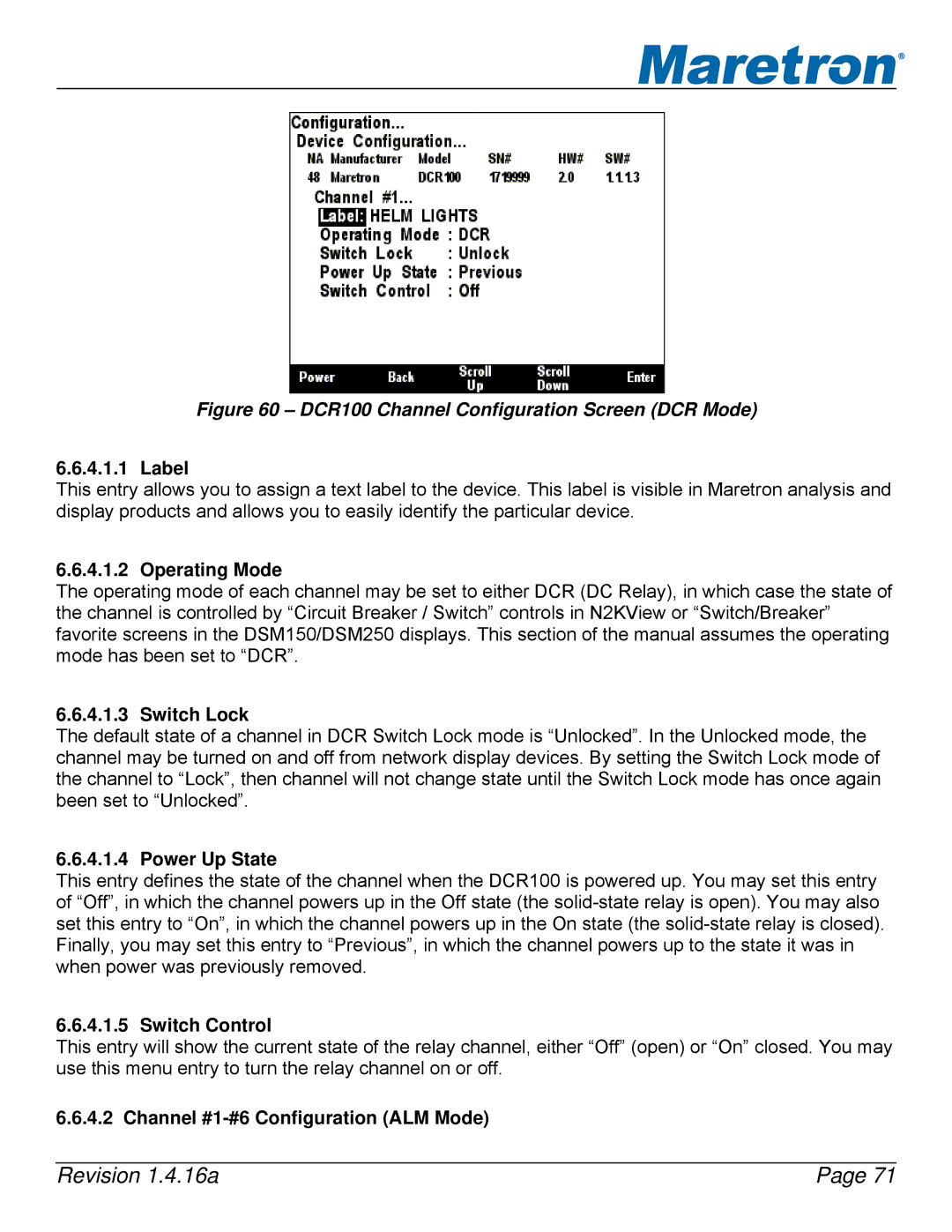
Figure 60 – DCR100 Channel Configuration Screen (DCR Mode)
6.6.4.1.1 Label
This entry allows you to assign a text label to the device. This label is visible in Maretron analysis and display products and allows you to easily identify the particular device.
6.6.4.1.2 Operating Mode
The operating mode of each channel may be set to either DCR (DC Relay), in which case the state of the channel is controlled by “Circuit Breaker / Switch” controls in N2KView or “Switch/Breaker” favorite screens in the DSM150/DSM250 displays. This section of the manual assumes the operating mode has been set to “DCR”.
6.6.4.1.3 Switch Lock
The default state of a channel in DCR Switch Lock mode is “Unlocked”. In the Unlocked mode, the channel may be turned on and off from network display devices. By setting the Switch Lock mode of the channel to “Lock”, then channel will not change state until the Switch Lock mode has once again been set to “Unlocked”.
6.6.4.1.4 Power Up State
This entry defines the state of the channel when the DCR100 is powered up. You may set this entry of “Off”, in which the channel powers up in the Off state (the
6.6.4.1.5 Switch Control
This entry will show the current state of the relay channel, either “Off” (open) or “On” closed. You may use this menu entry to turn the relay channel on or off.
6.6.4.2 Channel |
|
Revision 1.4.16a | Page 71 |