TigerSwitch 10/100/1000
Page
TigerSwitch 10/100/1000 Management Guide
Trademarks
Limited Warranty
Limited Warranty
Contents
Contents
Contents
Command Line Interface
Vii
Viii
Contents
Contents
Contents
Xii
Xiii
Xiv
Contents
Xvi
Tables
Xvii
Xviii
Figures
61. Displaying Vlan Information by Port Membership
Xix
Figures
Key Features
Key Features
Description of Software Features
Description of Software Features
Introduction
Description of Software Features
Introduction
System Defaults
System Defaults
System Defaults
Dhcp
Introduction
Configuration Options
Connecting to the Switch
Required Connections
Connecting to the Switch
Basic Configuration
Remote Connections
Console Connection
Setting Passwords
Manual Configuration
Setting an IP Address
Dynamic Configuration
Initial Configuration
Community Strings
Enabling Snmp Management Access
Initial Configuration
Trap Receivers
Saving Configuration Settings
Managing System Files
Managing System Files
Initial Configuration
Using the Web Interface
Configuring the Switch
Configuring the Switch
Home
Navigating the Web Browser Interface
Panel Display
Configuration Options
Main Menu
Main Menu
ACL
Lacp
STA
141
Vlan ID
DNS
Field Attributes
Displaying System Information
CLI Specify the hostname, location and contact information
System Information
Displaying Switch Hardware/Software Versions
Main Board
Management Software
Switch Information
Web Click System, Switch Information
Displaying Bridge Extension Capabilities
Setting the Switch’s IP Address
CLI Enter the following command
Web Click System, Bridge Extension
Command Attributes
Manual IP Configuration
Dhcp IP Configuration
Using DHCP/BOOTP
288
Downloading System Software from a Server
Managing Firmware
Operation Code Image File Transfer
Saving or Restoring Configuration Settings
10. Downloading Configuration Settings from a Server
Downloading Configuration Settings from a Server
CLI Use the reload command to restart the switch
Resetting the System
Configuring Sntp
Setting the System Clock
13. Sntp Configuration
14. Setting the Time Zone
Setting the Time Zone
Simple Network Management Protocol
Setting Community Access Strings
Specifying Trap Managers and Trap Types
Access Mode
16. Specifying Trap Managers and Trap Types
Configuring the Logon Password
User Authentication
17. Configuring the Logon Password
Configuring Local/Remote Logon Authentication
Command Usage
Radius Settings
18. Setting Local, Radius and Tacacs Authentication
Tacacs Settings
Configuring Https
Https Support
19. Https Settings
Replacing the Default Secure-site Certificate
Configuring the Secure Shell
Configuring the Switch
Generating the Host Key Pair
Field Attributes
20. SSH Host-Key Settings
SSH server includes basic settings for authentication
Configuring the SSH Server
21. SSH Server Settings
Configuring Port Security
Command Usage
22. Configuring Port Security
Configuring 802.1x Port Authentication
802.1x client Radius server
Displaying 802.1x Global Settings
23 .1x Information
111
Configuring 802.1x Global Settings
24 .1x Configuration
Configuring Port Authorization Mode
Authorized
25 .1x Port Configuration
Displaying 802.1x Statistics
Statistical Values
1x Statistics
26 .1x Statistics
Access Control Lists
Configuring Access Control Lists
CLI This example displays the 802.1x statistics for port
Setting the ACL Name and Type
CLI This example creates a standard IP ACL named bill
27. Naming and Choosing ACLs
28. Configuring Standard IP ACLs
Configuring a Standard IP ACL Command Attributes
Configuring an Extended IP ACL Command Attributes
Access Control Lists
29. Configuring Extended IP ACLs
120
Configuring a MAC ACL Command Attributes
Command Usage
30. Configuring MAC ACLs
Configuring ACL Masks
Command Usage
Specifying the Mask Type
This mask defines the fields to check in the IP header
Configuring an IP ACL Mask
Configuring the Switch
32. Configuring an IP based ACL
This mask defines the fields to check in the packet header
Configuring a MAC ACL Mask
33. Configuring a MAC based ACL
148
Binding a Port to an Access Control List
34. Mapping ACLs to Port Ingress/Egress Queues
Filtering Management Access
35. Filtering Management Access
Port Configuration
Displaying Connection Status
Field Attributes Web
Web Click Port, Port Information or Trunk Information
Field Attributes CLI
Current status
178
CLI This example shows the connection status for Port
Configuring Interface Connections
Port Configuration
Creating Trunk Groups
37. Configuring Port Attributes
Command Usage
38. Static Trunk Configuration
Statically Configuring a Trunk Command Usage
189
Enabling Lacp on Selected Ports Command Usage
39. Lacp Port Configuratio
190
Command Attributes
40. Lacp Aggregation Port Configuration
Counter Information
Displaying Lacp Port Counters
You can display statistics for Lacp protocol messages
Lacp Port Counter Information
41. Displaying Lacp Port Counters Information
Displaying Lacp Settings and Status for the Local Side
Internal Configuration Information
Lacp Settings
Link Passive 1 Active
42. Displaying Lacp Port Information
Displaying Lacp Settings and Status for the Remote Side
Neighbor Configuration Information
Lacp Remote Side Settings
43. Displaying Remote Lacp Port Information
100
101
Setting Broadcast Storm Thresholds
44. Enabling Port Broadcast Control
102
103
Configuring Port Mirroring
104
Configuring Rate Limits
105
Command Attribute
106
Showing Port Statistics
Port Statistics
107
108
Rmon Statistics
109
47. Displaying Port Statistics
110
48. Displaying Etherlike and Rmon Statistics
111
Setting Static Addresses
Address Table Settings
112
CLI This example shows statistics for port
49. Mapping Ports to Static Addresses
113
114
Displaying the Address Table
Changing the Aging Time
115
CLI This example sets the aging time to 400 seconds
116
Spanning Tree Algorithm Configuration
117
Displaying Global Settings
118
119
52. Displaying the Spanning Tree Algorithm
120
Configuring Global Settings
Global settings apply to the entire switch
121
122
Basic Configuration of Global Settings
123
Root Device Configuration
124
Configuration Settings for Rstp
125
53. Configuring the Spanning Tree Algorithm
126
Displaying Interface Settings
Rules defining port status are
127
AD B
128
129
Configuring Interface Settings
130
CLI This example shows the STA attributes for port
131
132
Configuring Multiple Spanning Trees
133
CLI This example sets STA attributes for port
134
Vlan ID Vlan to assign to this selected MST instance. Range
135
136
137
Displaying Interface Settings for Mstp
138
139
Configuring Interface Settings for Mstp
140
58. Mstp Port Configuration
Overview
Vlan Configuration
141
CLI This example sets the Mstp attributes for port
Assigning Ports to VLANs
142
143
144
Forwarding Tagged/Untagged Frames
145
CLI This example enables Gvrp for the switch
Enabling or Disabling Gvrp Global Setting
Displaying Basic Vlan Information
146
Displaying Current VLANs
Command Attributes Web
147
Web Click VLAN, 802.1Q VLAN, Basic Information
148
Command Attributes CLI
149
Creating VLANs
CLI This example creates a new Vlan
150
151
Adding Static Members to VLANs Vlan Index
152
63. Configuring Vlan Port Attributes
153
Adding Static Members to VLANs Port Index
154
Configuring Vlan Behavior for Interfaces
155
156
157
65. Configuring Vlan Ports
CLI This example enables private VLANs
Configuring Private VLANs
158
Enabling Private VLANs
Configuring Protocol-Based VLANs
Configuring Uplink and Downlink Ports
159
Configuring Protocol Groups
160
Create a protocol group for one or more protocols
Mapping Protocols to VLANs
161
69. Mapping Protocols to VLANs
162
Class of Service Configuration
Setting the Default Priority for Interfaces
163
164
CLI This example assigns a default priority of 5 to port
165
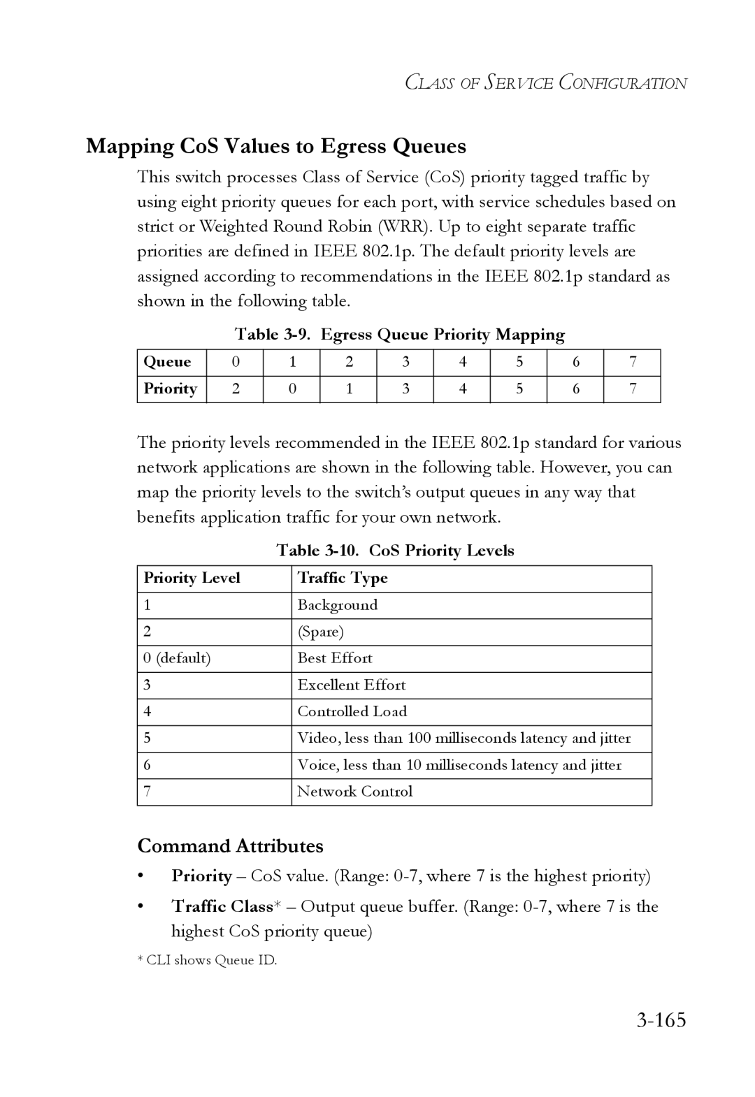
Mapping CoS Values to Egress Queues
Egress Queue Priority Mapping
10. CoS Priority Levels
166
71. Configuring Ports and Trunks for Class of Service
167
Selecting the Queue Mode
168
Setting the Service Weight for Traffic Classes
169
Mapping Layer 3/4 Priorities to CoS Values
170
Selecting IP Precedence/DSCP Priority
Mapping IP Precedence
171
11. IP Precedence Prioruty
172
75. Mapping IP Precedence to Class of Service Values
173
Mapping Dscp Priority
174
76. Mapping IP Dscp Priority to Class of Service Values
175
Mapping IP Port Priority
78. IP Port Priority Mapping
176
Mapping CoS Values to ACLs
177
13. CoS to ACL Mapping
178
Changing Priorities Based on ACL Rules
179
79. Changing Priorities Based on ACL Rules
180
181
Multicast Filtering
Configuring Igmp Snooping and Query Parameters
Layer 2 Igmp Snooping and Query
182
183
184
80. Configuring Internet Group Management Protocol
Command Attributes
185
Displaying Interfaces Attached to a Multicast Router
Specifying Static Interfaces for a Multicast Router
186
187
Displaying Port Members of Multicast Services
188
Assigning Ports to Multicast Services
84. Specifying Multicast Port Membership
189
Configuring Domain Name Service
Configuring General DNS Server Parameters
190
191
192
85. Configuring DNS
193
Configuring Static DNS Host to Address Entries
86. Mapping IP Addresses to a Host Name
194
195
Displaying the DNS Cache
Web Select DNS, Cache
196
Accessing the CLI
Using the Command Line Interface
Telnet Connection
Using the Command Line Interface
This section describes how to enter CLI commands
Entering Commands
Keywords and Arguments
Minimum Abbreviation
Getting Help on Commands
Command Completion
Showing Commands
Negating the Effect of Commands
Using Command History
Partial Keyword Lookup
Understanding Command Modes
Exec Commands
Command Modes
Configuration Commands
Mode Command Prompt
Configuration Commands
Keystroke Function
Command Line Processing
Command Group Index
Command Groups
255
Line Command Syntax
Line Commands
Command Mode
Default Setting
Line
Syntax Line console vty
Login
Related Commands
Syntax Login local no login
Username 4-35 password
Password
Syntax Password 0 7 password no password
No password is specified
Login 4-16password-thresh4-19
Exec-timeout
Syntax Exec-timeout seconds no exec-timeout
CLI No timeout Telnet 10 minutes
To set the timeout to two minutes, enter this command
Password-thresh
Syntax Password-thresh threshold no password-thresh
Default value is three attempts
Syntax Silent-time seconds no silent-time
Silent-time
Databits
To specify 7 data bits, enter this command
Syntax Databits 7 8 no databits
Seven data bits per character Eight data bits per character
Parity
To specify no parity, enter this command
Syntax Parity none even odd no parity
None No parity Even Even parity Odd Odd parity
Speed
To specify 57600 bps, enter this command
Syntax Speed bps no speed
Auto
Disconnect
Stopbits
Syntax Stopbits 1
Syntax Disconnect session-id
Syntax Show line console vty
Show line
Enable
General Commands
General Commands
Syntax Enable level
Disable Enable password
Disable
Normal Exec
None
Show history
Configure
Reload
This command restarts the system
This example shows how to reset the switch
This command resets the entire system
This command returns to Privileged Exec mode
End
Exit
This command exits the configuration program
Quit
Any
System Management Commands
This example shows how to quit a CLI session
System Mangement Commands
Device Designation Commands
Device Designation Commands
Prompt
Syntax Prompt string no prompt
User Access Commands
User Access Commands
Hostname
Syntax Hostname name no hostname
Username
Default is level Default password is super
Enable password
10. IP Filter Commands
IP Filter Commands
All addresses
Management
Show management
11. Web Server Command
Web Server Commands
Syntax No ip http server Default Setting
Default Setting Command Mode
Ip http port
Ip http server
Syntax No ip http secure-server Default Setting
Ip http secure-server
Ip http port Copy tftp https-certificate
Ip http secure-port4-44 Copy tftp https-certificate
Portnumber The UDP port used for HTTPS/SSL. Range
Ip http secure-port
443
Ip http secure-server4-42
12. Secure Shell Commands
Secure Shell Commands
12. Secure Shell Commands
System Management Commands
Syntax Ip ssh server no ip ssh server Default Setting
Disabled
Ip ssh server
Syntax Ip ssh timeout seconds no ip ssh timeout
Ip ssh timeout
Ip ssh crypto host-key generate 4-52 show ssh
Seconds
Ip ssh authentication-retries
Exec-timeout4-18 show ip ssh
Show ip ssh
Ip ssh server-key size
Delete public-key
Syntax Delete public-key username dsa rsa
Syntax Ip ssh crypto host-key generate dsa rsa
Ip ssh crypto host-key generate
Dsa DSA key type Rsa RSA key type
Generates both the DSA and RSA key pairs
Ip ssh crypto zeroize
Use this command to clear the host key from memory i.e. RAM
Ip ssh crypto zeroize 4-53 ip ssh save host-key4-54
Syntax Ip ssh crypto zeroize dsa rsa
Ip ssh save host-key
Show ip ssh
Syntax Ip ssh save host-key dsa rsa
13. SSH Information
Show ssh
Show public-key
Syntax Show public-key user username host
Username Name of an SSH user. Range 1-8 characters
RSA
Shows all public keys
14. Event Logging Commands
Event Logging Commands
Syntax No logging on Default Setting
Logging on
Logging history 4-59 clear logging
Logging history
Logging host
Flash errors level 3 RAM warnings level 7
Syntax No logging host hostipaddress
Hostipaddress The IP address of a syslog server
Syntax No logging facility type
Logging facility
Clear logging
Logging trap
Syntax Logging trap level no logging trap
Syntax Clear logging flash ram
Show logging
Show logging
Syntax Show logging flash ram sendmail trap
Following example displays settings for the trap function
Smtp Alert Commands
15. Smtp Alert Commands
Show logging sendmail
Syntax No logging sendmail host ipaddress
Logging sendmail host
Logging sendmail source-email
Logging sendmail level
Syntax Logging sendmail level level
Syntax Logging sendmail source-email email-address
Syntax No logging sendmail destination-email email-address
Logging sendmail destination-email
Syntax No logging sendmail Default Setting
Logging sendmail
Show logging sendmail
16. Time Commands
Time Commands
Sntp server
Syntax Sntp server ip1 ip2 ip3
Sntp poll 4-72 show sntp
Sntp poll
Related Commands
Sntp client
Syntax Sntp poll seconds no sntp poll
Disabled
Syntax No sntp broadcast client Default Setting
Sntp broadcast client
Show sntp
Show sntp
Clock timezone
Calendar set
This command displays the system clock
Show calendar
Syntax
System Status Commands
Show startup-config
17. System Status Commands
Command Usage
Show running-config4-80
Show running-config
Show startup-config4-77
Show system
This command displays system information
Show version
Show users
18. Frame Size Commands
Frame Size Commands
Syntax No jumbo frame Default Setting
Jumbo frame
19. Flash/File Commands
Flash/File Commands
Copy
Command Usage
Following example shows how to download a configuration file
This command deletes a file or image
Filename Name of the configuration file or image name
Delete
Syntax Dir boot-rom config opcode filename
This command displays a list of files in flash memory
Dir
Dir Delete public-key4-51
Following example shows how to display all file information
Whichboot
Syntax Boot system boot-romconfig opcode filename
Boot system
Authentication Sequence
Authentication Commands
Dir 4-90 whichboot
20. Authentication Commands
Local
Authentication login
22. Radius Client Commands
Username for setting the local user names and passwords
Radius Client
Radius-server host
10.1.0.1
Radius-server port
Syntax Radius-server port portnumber no radius-server port
1812
Radius-server key
Radius-server retransmit
Syntax Radius-server key keystring no radius-server key
Show radius-server
Radius-server timeout
TACACS+ Client
23. TACACS+ Client Commands
Tacacs-server host
Hostipaddress IP address of a TACACS+ server
Syntax Tacacs-server port portnumber no tacacs-server port
Tacacs-server port
Tacacs-server key
Show tacacs-server
Syntax Tacacs-server key keystring no tacacs-server key
Port Security Commands
24. Port Security Commands
Port security
Interface Configuration Ethernet
Status Disabled Action None Maximum Addresses
25 .1x Port Authentication Commands
802.1x Port Authentication
Authentication dot1x default
Syntax Dot1x default Command Mode
Dot1x default
Default Command Mode
Dot1x max-req
Interface Configuration
Default
Dot1x port-control
Force-authorized
Syntax Dot1x re-authenticate interface
Dot1x re-authenticate
Dot1x operation-mode
Ethernet unit/port
Dot1x timeout quiet-period
Dot1x re-authentication
Syntax No dot1x re-authentication Command Mode
Seconds The number of seconds. Range
Dot1x timeout tx-period
Dot1x timeout re-authperiod
Show dot1x statistics interface interface
Show dot1x
State- Current state including initialize, reauthenticate
Authenticator State Machine
113
Access Control Lists
Access Control List Commands
Access Control List Commands
26. Access Control List Commands
Masks for Access Control Lists
27. IP ACL Commands
IP ACLs
EXT-ACL
Syntax No access-list ip standard extended aclname
Access-list ip
Standard ACL
Permit, deny Ip access-group4-129 show ip access-list4-123
No permit deny tcp
Access-list ip
Extended ACL
122
Access-list ip mask-precedence
Show ip access-list
Syntax Show ip access-list standard extended aclname
Syntax No access-list ip mask-precedence in out
Mask IP ACL 4-125 ip access-group4-129
IP Mask
Syntax No mask protocol
126
127
Syntax Show access-list ip mask-precedence in out
Show access-list ip mask-precedence
Ip access-group
Syntax No ip access-group aclname in out
Mask IP ACL
Map access-list ip
Show ip access-group
Show ip access-list4-123
This command shows the ports assigned to IP ACLs
Queue cos-map4-260 Show map access-list ip
Show map access-list ip
Syntax Show map access-list ip interface
Map access-list ip
Match access-list ip
Match access-list ip
Show marking
Show marking
MAC ACLs
28. MAC ACL Commands
Syntax No access-list mac aclname
Access-list mac
Any host destination destination address-bitmask
Permit, deny MAC ACL
MAC ACL
Access-list mac mask-precedence
Show mac access-list
This command displays the rules for configured MAC ACLs
Syntax Show mac access-list aclname
Mask MAC ACL
Mask MAC ACL 4-140 mac access-group4-144
MAC Mask
142
Show access-list mac mask-precedence
Syntax Show access-list mac mask-precedence in out
This example creates an Egress MAC ACL
Mac access-group
Syntax Mac access-group aclname in out
Show mac access-list4-139
Map access-list mac
Show mac access-group
This command shows the ports assigned to MAC ACLs
Syntax No map access-list mac aclname cos cos-value
Show map access-list mac
Queue cos-map4-260 Show map access-list mac
Syntax Show map access-list mac interface
Match access-list mac
Show access-list
ACL Information
29. ACL Information
Show access-group
Snmp Commands
This command shows the port assignments of ACLs
30. Snmp Commands
Syntax Snmp community string rorw no snmp community string
Snmp community
Snmp location
Snmp contact
Syntax Snmp contact string no snmp contact
Syntax Snmp-server location text no snmp-server location
Host Address None Snmp Version
Snmp host
Consoleconfig#snmp-server host 10.1.19.23 batman
Snmp enable traps
Syntax No snmp enable traps authentication link-up-down
Issue authentication and link-up-down traps
Show snmp
This command checks the status of Snmp communications
156
31. DNS Commands
DNS Commands
Ip host
No static entries
This example maps two address to a host name
Ip domain-name
Clear host
Syntax Clear host name
Syntax Ip domain-name name no ip domain-name
Syntax No ip domain-list name
Ip domain-list
Ip domain-name4-159
Server-address1- IP address of domain-name server
Ip name-server
Syntax No ip domain-lookup Default Setting
Ip domain-lookup
Ip domain-name4-159 ip domain-lookup4-163
Ip domain-name4-159 ip name-server4-162
Show hosts
This command displays entries in the DNS cache
This command displays the configuration of the DNS server
Show dns
Show dns cache
Clear dns cache
This command clears all entries in the DNS cache
167
32. Interface Commands
Interface Commands
Description
Interface
Port-channel channel-idRange
Syntax Description string no description
Interface Configuration Ethernet, Port Channel
Speed-duplex
Following example adds a description to port
Syntax No negotiation Default Setting
Negotiation
Negotiation 4 -170 capabilities 4
Capabilities 4 -172speed-duplex 4
Following example configures port 11 to use autonegotiation
Capabilities
Flow control enabled
Syntax No flowcontrol Default Setting
Flowcontrol
Negotiation 4 -170speed-duplex 4 -169 flowcontrol 4
Syntax Combo-forced-mode mode no combo-forced-mode
Following example enables flow control on port
Combo-forced-mode
Negotiation 4 Capabilities flowcontrol, symmetric
All interfaces are enabled
Syntax No shutdown Default Setting
Following example disables port
Shutdown
Switchport broadcast packet-rate
Port-channel channel-idRange Default Setting
This command clears statistics on an interface
Clear counters
Following example clears statistics on port
Show interfaces status
This command displays the status for an interface
Syntax Show interfaces status interface
Shows the status for all interfaces
Show interfaces counters
This command displays interface statistics
Syntax Show interfaces counters interface
Shows the counters for all interfaces
180
Syntax Show interfaces switchport interface
Show interfaces switchport
This example shows the configuration setting for port
Shows all interfaces
Shows if acceptable Vlan frames include all types or
33. Mirror Port Commands
Mirror Port Commands
Interface Configuration Ethernet, destination port
Port monitor
Unit Switch unit Port Port number
This command displays mirror information
Show port monitor
Syntax Show port monitor interface
Rate Limit Commands
Following shows mirroring configured from port 6 to port
34. Rate Limit Commands
Mbps
Rate-limit
35. Link Aggregation Commands
Link Aggregation Commands
General Guidelines
Guidelines for Creating Trunks
Syntax Channel-group channel-idno channel-group
Channel-group
Channel-id- Trunk index Range
Current port will be added to this trunk
Lacp
Syntax No lacp Default Setting
191
32768
Lacp system-priority
Lacp admin-keyEthernet Interface
Lacp admin-key Port Channel
Syntax Lacp admin-key key no lacp admin-key
Interface Configuration Port Channel
Lacp port-priority
This command displays Lacp information
Show lacp
Port Channel all
197
198
199
Address Table Commands
36. Adress Table Commands
200
201
Mac-address-table static
Mac-address- MAC address
Vlan-id- Vlan ID Range
Show mac-address-table
Clear mac-address-table dynamic
202
Mac-address- MAC address Mask Bits to match in the address
203
Mac-address-table aging-time
204
Show mac-address-table aging-time
Spanning Tree Commands
37. Spanning Tree Commands
205
Spanning-tree
Spanning tree is enabled
206
No spanning-tree
Spanning-tree mode
207
Rstp
208
209
Spanning-tree forward-time
Spanning-tree hello-time
Spanning-tree max-age
210
211
Spanning-tree priority
Spanning-tree pathcost method
212
Long method
This command limits the maximum transmission rate for BPDUs
Spanning-tree mst-configuration
Spanning-tree transmission-limit
213
MST Configuration
Mst vlan
214
215
Mst priority
Name
Switch’s MAC address
216
Syntax Name name
217
Revision
Revision 4
Syntax Revision number
Max-hops
218
Name 4
Syntax No spanning-tree spanning-disabled Default Setting
Spanning-tree spanning-disabled
Spanning-tree cost
219
220
Spanning-tree port-priority
Priority The priority for a port. Range 0-240, in steps
128
Spanning-tree edge-port
Syntax No spanning-tree edge-port Default Setting
221
Spanning-tree cost 4
Spanning-tree portfast
Syntax No spanning-tree portfast Default Setting
222
Spanning-tree portfast 4
Spanning-tree link-type
223
Spanning-treeedge-port 4
224
Spanning-tree mst cost
Spanning-tree mst port-priority 4
225
Spanning-tree mst port-priority
226
Spanning-tree mst cost 4
Spanning-tree protocol-migration
Port-channel channel-idRange Command Mode
227
Syntax Spanning-tree protocol-migration interface
Show spanning-tree
228
Syntax Show spanning-tree interface mst instanceid
229
This command shows the multiple spanning tree configuration
Show spanning-tree mst configuration
Syntax Show spanning-tree mst configuration Command Mode
230
38. Vlan Commands
Vlan Commands
Editing Vlan Groups
231
232
Vlan database
Show vlan 4
Vlan Database Configuration
By default only Vlan 1 exists and is active
233
Vlan
Configuring Vlan Interfaces
40. Configuring Vlan Interfaces
234
Interface vlan
235
Syntax Interface vlan vlan-id
Shutdown 4
Syntax Switchport mode trunk hybrid no switchport mode
Switchport mode
All ports are in hybrid mode with the Pvid set to Vlan
Switchport acceptable-frame-types 4
Switchport mode 4
Switchport acceptable-frame-types
237
All frame types
Switchport ingress-filtering
Syntax No switchport ingress-filtering Default Setting
238
239
Switchport native vlan
240
Switchport allowed vlan
Switchport forbidden vlan
241
No VLANs are included in the forbidden list
242
Displaying Vlan Information
Show vlan
41. Displaying Vlan Information
Following example shows how to display information for Vlan
42. Protocol-based Vlan Commands
243
Protocol-vlan protocol-group Configuring Groups
No protocol groups are configured
244
Protocol-vlan protocol-group Configuring Interfaces
245
No protocol groups are mapped for any interface
Show protocol-vlan protocol-group
246
Syntax Show protocol-vlan protocol-group group-id
Group-id- Group identifier for a protocol group. Range
247
This shows protocol group 1 configured for IP over Ethernet
Show interfaces protocol-vlan protocol-group
Mapping for all interfaces is displayed
248
43. Private Vlan Commands
Pvlan
No private VLANs are defined
This command displays the configured private Vlan
249
Show pvlan
44. Gvrp and Bridge Extension Commands
Gvrp and Bridge Extension Commands
Syntax No bridge-ext gvrp Default Setting
250
Show bridge-ext
251
Show gvrp configuration
Switchport gvrp
Syntax No switchport gvrp Default Setting
Syntax Show gvrp configuration interface
253
Garp timer
Show garp timer 4
Show garp timer
Syntax Show garp timer interface
Shows all Garp timers
Garp timer 4
Priority Commands
45. Priority Commands
255
Switchport priority default
Priority Commands Layer
46. Priority Commands Layer
256
257
Syntax Queue mode strict wrr no queue mode
Queue mode
Weighted Round Robin
258
259
Queue bandwidth
Show queue bandwidth 4
Queue cos-map
260
This command shows the current queue mode
Show queue mode
261
Show queue cos-map 4
262
This command shows the class of service priority map
Show queue bandwidth
Show queue cos-map
Priority Commands Layer 3
47. Priority Commands Layer 3
263
264
Syntax Map ip port no map ip port Default Setting
265
Syntax No map ip precedence Default Setting
266
List below shows the default priority mapping
267
Syntax No map ip dscp Default Setting
268
Map ip dscp Interface Configuration
269
Use this command to show the IP port priority map
Show map ip port
Syntax Show map ip port interface
270
This command shows the IP precedence priority map
Show map ip precedence
Syntax Show map ip precedence interface
271
This command shows the IP Dscp priority map
Show map ip dscp
Syntax Show map ip dscp interface
Igmp Snooping Commands
Multicast Filtering Commands
48. Multicast Filtering Commands
49. Igmp Snooping Commands
273
Following example enables Igmp snooping
Ip igmp snooping
No ip igmp snooping
Ip igmp snooping vlan static
274
275
Following configures the switch to use Igmp Version
Ip igmp snooping version
Igmp Version
276
Show ip igmp snooping
Show mac-address-table multicast
Igmp Query Commands Layer
50. Igmp Query Commands Layer
277
278
Syntax No ip igmp snooping querier Default Setting
Ip igmp snooping querier
Ip igmp snooping query-count
279
Following shows how to configure the query count to
Ip igmp snooping query-interval
Ip igmp snooping query-max-response-time 4
Seconds The report delay advertised in Igmp queries. Range
280
Ip igmp snooping query-max-response-time
Switch must use IGMPv2 for this command to take effect
281
Ip igmp snooping router-port-expire-time
51. Static Multicast Routing Commands
Static Multicast Routing Commands
282
Ip igmp snooping vlan mrouter
283
Displays multicast router ports for all configured VLANs
Show ip igmp snooping mrouter
Syntax Show ip igmp snooping mrouter vlan vlan-id
Basic IP Configuration
IP Interface Commands
52. Basic IP Configuration commands
284
285
Interface Configuration Vlan
Ip address
IP address Netmask
286
This command submits a Bootp or Dhcp client request
Ip dhcp restart
Ip dhcp restart 4
Ip default-gateway
Syntax Ip default-gateway gateway no ip default-gateway
287
288
Show ip interface
Show ip redirects
289
This command has no default for the host
Ping
Syntax Ping host count countsize size
Interface 4
290
291
Authentication
Software Features
Dhcp Client Port Configuration
Flow Control
Additional Features
Class of Service
Port Mirroring
Rate Limits
Standards
Management Features
In-Band Management
Out-of-Band Management
Management Information Bases
Table B-1. Troubleshooting Chart
Appendix B Troubleshooting
Troubleshooting
Glossary-1
Glossary-2
Glossary-3
Glossary-4
Glossary-5
Glossary-6
Glossary-7
User Datagram Protocol UDP
Glossary-8
Virtual LAN Vlan
XModem
Index-1
Numerics
Igmp
Index-2
Snmp Snmp
Index-3
Index-4
Page
For Technical SUPPORT, Call