Release
Copyright Information
TA B L E O F CO N T E N T S
Talkswitch Configuration
Using Talkswitch
Receiving calls without the auto attendant
Call Detail Record CDR Logging
Troubleshooting and Support
WHAT’S in this GUIDE?
What you should know
VoIP installation
Single unit installation
Networked units installation
Connecting devices
Where to go for further information
Finding the Information YOU Need
Guide Conventions
Text elements
TA L K S W I T CH Installation
Talkswitch Package Contents
Configuration Software System Requirements
Unit Front Panel
Light State Description
TalkSwitch 24-CA
Unit Back Panel
Connection on page 9, 1.9 Networking TalkSwitch units on
Connecting devices to the music jack on
Information, see 1.8.4 Connecting to the PA public
Information, see 1.8.2 Connecting local extension
Upgrading the TalkSwitch software and firmware
Installing the Configuration Software
Installing the software for the first time
Installing a memory card on
About TalkSwitch software version
Check current version
Click View System Information
Download new software and firmware
Initial Configuration
File Update Firmware
Updating the firmware
Connect Talkswitch to a Network or a PC
Ethernet connection
USB Connection
Ethernet connection
Serial connection
USB connection
Internet connection
Serial connection
Internet connection
File connection
Click Connect
Things to consider when placing your TalkSwitch
Connecting Devices
Restore Firmware button
Wiring
Connecting incoming telephone lines
Connecting local extension telephones and other devices
Connecting a regular single-line telephone
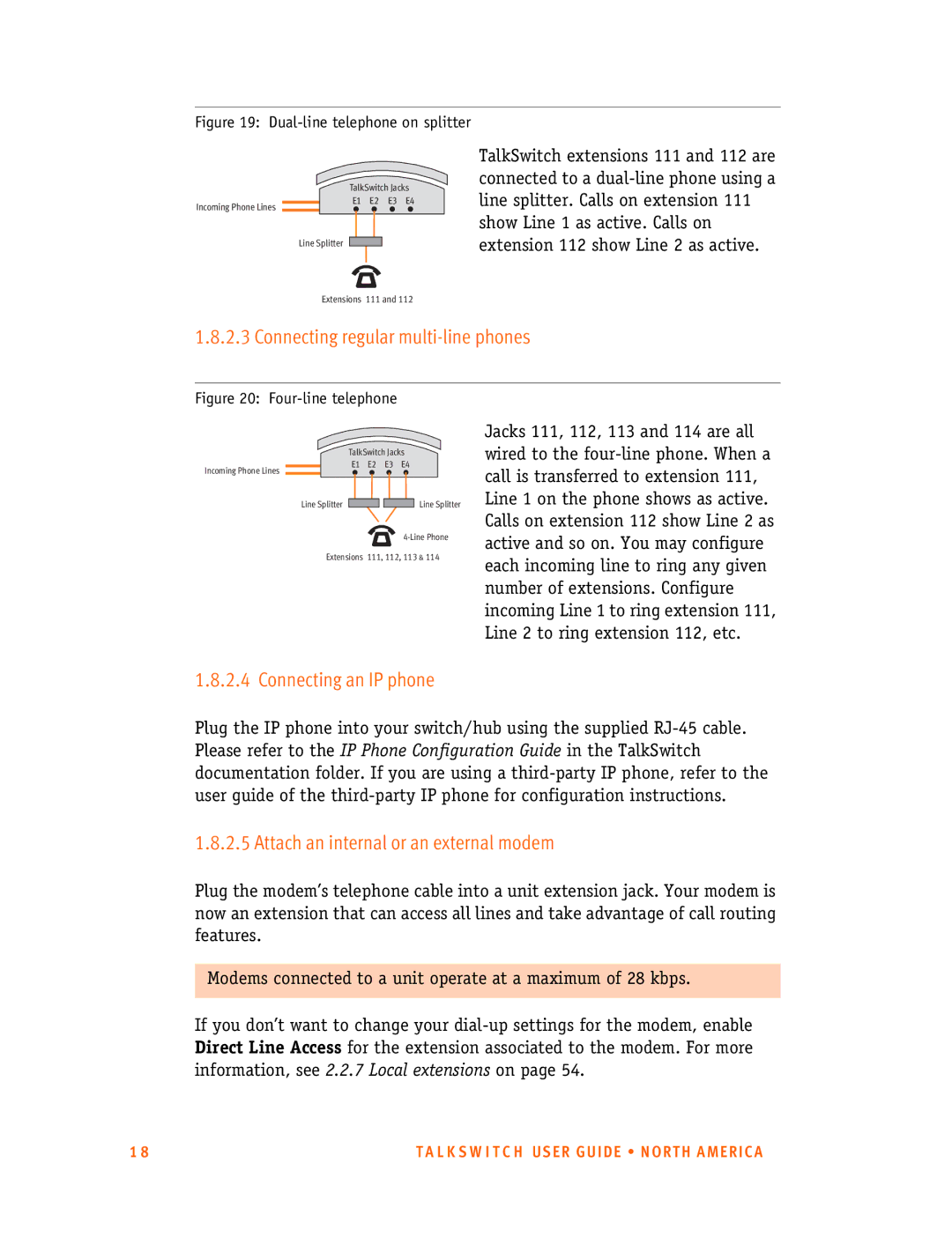
Connecting a regular dual-line telephone
Connecting regular multi-line phones
Connecting an IP phone
Attach an internal or an external modem
Connecting fax machines
Option 1 Dedicated Fax Line
Option 2 Distinctive Ring
Here’s how the TalkSwitch handles incoming calls
Option 3 Automatic fax detection via the auto attendant
Connecting to the PA public address jack
Networking Talkswitch Units on a LAN
Connecting devices to the music jack
Connecting TalkSwitch units to a LAN
Ethernet switch
Power up all the TalkSwitch units
Setting or changing the unit ID
How unit IDs affect system extension numbers
Keys Result
Keep track of the lines and extensions
Unit ID
Outgoing line hunt groups
Configuration settings
Optimizing the system for networked use
Auto attendants
Installing a Memory Card
Memory card
Upgrading Talkswitch Units
Diagnostics for the lights flashing on the unit front panel
What the Flashing Lights Mean
Verifying the Connections
System Configuration
Configuration screen
Settings
TalkSwitch
Exit Closes the configuration software
File Menu
Help Menu
Installed
Tools Menu
Usage
System
Configuration navigation
About
Information
Configuration navigation
See 2.2.10 On-Hold
Feature Description
See 2.4.2 Auto
See 2.5 Call Back/Call
System Information
Administration
Click the next to System Information Administration
Call Detail Record CDR Logging on
To enter a new password
To change the password
To delete a password
IP Configuration
Click the next to System Information -IP Configuration
Automatic IP configuration
Public WAN IP Address
Current public WAN IP address
Fully Qualified Domain Name
Telephone Lines
Public WAN IP address-checker server name
Click System Information Telephone Lines
Phone numbers section
Way Calling/Conference
Line hunt groups
Calibrate Lines button
Hunt group configuration
Select System Information -Line Hunt Groups
Automatic Route Selection and Toll Restriction
What is Automatic Route Selection ARS?
What is Toll Restriction?
Planning Automatic Route Selection and Toll Restriction
Information Auto Route Selection
ARS leading digits
Examples of leading digits
Set local extension hunt group access
Direct Line Access
Information Administration
Emergency Service Numbers section
Password Protection
Telephone Line 3-Way Calling Services
Dedicated fax line
Restrict access to premium services
Fax information
Distinctive Ring fax detection
Dedicated fax line
Automatic fax detection with the auto attendant
Select System Information -Fax Information
System Information Telephone Lines
Fax information
Distinctive ring fax detection
Select System Information -Telephone Lines
Automatic fax detection
Click Fax Information
Select Call Handling -Auto Attendant
Local extensions
Fax routing
Additional fields Caller ID Information section
Configuring a local extension for use with a IP phone
Select System Information -Local Extensions
Last name/First name
For VoIP calls, use this number
Phone Type
Supported by TalkSwitch
Direct Line Access... button
Hunt Group Access... button
Remote extensions
Select System Information -Remote Extensions
Use Same Line Connect
Remote extensions
Forwarding calls to a remote extension
Transferring calls from a remote extension
Extension ring groups
Ring groups features
Setting up extension ring groups
Select System Information -Extension Ring Groups
Different uses for extension ring groups
Identify types of calls by different ring patterns
On-Hold/Ringback
External audio source
Forwarding calls to a ring group
Select System Information On-Hold/Ringback
Music port
On-Hold Settings
Internal audio file
Set the volume for Music on Hold
Transfer Settings
Voicemail
Mailbox options
Voicemail notification
Dialed notification
Remote Phone
Notification Settings button
Dialed Notification
Configure Notification Options button
Dial notification phone number using
If attempt unsuccessful, try again
Message waiting light
Mail notification
Click on the Message Waiting Light tab
Click on the E-mail Notification tab
Mail notification tab
To modify an e-mail address
To add an e-mail address
Example of an e-mail notification
To remove an e-mail address
Global Settings
Select Voicemail Global Settings
More e-mail settings
Global Message Waiting Indicator
Voicemail manager
Reset Mailboxes button
Mailbox data
Call Handling
Modes
Select Call Handling Modes
To set holiday mode
Click Settings
Adding/configuring an auto attendant
Auto attendant
Configuring auto attendant
Record, play or erase auto attendant messages
Record Instructions button
Load Auto Attendant button
Erase Instructions button
Tools Memory Usage Auto Attendant
Select routing options for each auto attendant
View Auto Attendant Time Usage
If the caller selects 0 then
English, 2 for Spanish. In this example, you
If a fax call is detected then
If 6 is dialed
Additional features at the auto attendant
No selection was made at the auto attendant
If 7 is dialed
Configure incoming calls during mode 1, 2 and holiday mode
Select Call Handling -Telephone Lines
Select Business Hours
Adjust Sequence... button
Go to voice mailbox
VoIP Numbers
Play auto attendant or Go to voice mailbox
Call Cascade
Local extensions
Select Call Handling Local Extensions
Busy No Answer Answered Do Not Disturb
Busy tab
No Answer tab
Answered tab
Remote extensions
Remote extension call cascade
L K S W I T C H US E R G U I D E N O R T H a M E R I C a
Extension ring groups call cascade
Extension ring group call cascade
Go to auto attendant Queue at ring group
Hang up Go to VoIP location
If I am away from my desk
Call cascade examples
If my extension is busy
Screening calls from a remote extension
Two call back methods
Call BACK/CALL Bridge
If I don’t want to be disturbed only local extensions
How it works
Auto call back
Select Call Back/Call Bridge Auto Call Back
Use Announced Message
Configuring auto call back
Prompted call back
Select Call Back/Call Bridge Prompted Call Back
Accessing and using prompted call back from a telephone
Call bridge
Activating call bridge
Options
Permissions
To add permissions for users Select Options Permissions
Select the user and click Modify
Audio Controls
Line Controls
Extension Controls
Transfer Options
Transferring from a home phone
Transfer and clear
Remote transfer
Call Back ring return
Miscellaneous
Caller in queue reminder
If being used with another PBX PBX extension length
Setting up TalkSwitch behind an existing PBX
Auto Attendant Transfer Prompts
Troubleshooting
Other options include
SIP Server Registration
Double Flash time
Auto Attendant Adjustments
Transmitted Flash length
Way Calling wait time
Dtmf Detection
Troubleshooting Advanced
Auto Route Selection
Minimum required time to detect a Dtmf digit
Line CPC/Disconnect Clear
Ringback Control
Fax Detection
VoIP Ports IP Signalling Port
Starting RTP Port
Receiving calls using the auto attendant
I N G TA L K S W I T CH
Office Making and Receiving Calls Using AN Analog Phone
Receiving calls without the auto attendant
Receiving calls at a local extension
Place out-of-office calls from a local extension
Restrictions
Unscreened transfer
Placing calls on hold at a local extension
Transferring calls from an extension
Place calls on hold
Screened transfer
Unscreened Transfer
Retrieving a parked call at another local extension
Parking and retrieving calls at a local extension
Parking a call
Screened Transfer
Using call park with the paging option
Queuing and retrieving callers
Queuing calls to a single extension
Using call waiting
Queuing callers to an extension ring group
Two local TalkSwitch extensions and one outside caller
Conference calling
Two outside callers and one local extension
Office Making and Receiving Calls Using AN IP Phone
Making calls from a local IP extension IP phone
Receiving calls at a local IP extension
Hold and transfer
Hold
Transfer from a IP extension to any outside number
Call park Parking and retrieving callers
Parking a caller
Retrieving a parked call
Using the TalkSwitch call waiting feature
Conference calling with TalkSwitch
Two TalkSwitch local extensions and one outside caller
Making and Receiving Calls Using Voip
Transferring calls on parallel-connected phones
Modems and Telephone Line Access
Manual call forwarding
Three ways to forward calls
Automatic call forwarding
Conditional call forwarding
Transferring calls from a remote extension
Screening options for forwarded calls
Forwarding calls with screening
Calls over VoIP with IP phones and Gateways
Making calls
Using the Voicemail System
Activating voicemail boxes
Receiving calls
Retrieving messages and accessing a voice mailbox
Press Transfer or xfer
Press 1 to listen to messages
Press 2 to change greeting options
Recording an announcement on a regular or an IP phone
Press 3 to change personal options
Press 4 to record your name for the dial-by-name directory
Music on Hold
Pager and cell phone notification
Music on hold and call forwarding to remote extensions
Mode Switching Options
Manual mode switching
Automatic mode switching using the time scheduler
Using call bridge
Bridge session, press # # before hanging up
Using call back
Activate call back
Accepting the call back
CA L L D E T a I L RE CO RD C D R LO G G I N G
Enabling Call Detail Record CDR Logging
Web interface Store to File on TalkSwitch
File Save to TalkSwitch
Retrieving Data
Log in window
Serial interface Real-time to Serial Port
CDR web interface
Connecting
Click on Transfer Capture Text
Analyzing the Data
IP phone press * * , then dial * 88 + Account Number
Example
VO I P I N F O R M a T I O N
Introduction to Voip
Optimizing Your IP Network for Voip
Broadband connection
Router/NAT/firewall
Connecting to a LAN and IP network
Confirm sufficient network capacity for VoIP
Confirm router/firewall path for voice data
UDP
Prioritize your voice traffic
Setting UP a Voip Network
Connect TalkSwitch or SIP-compatible gateways
Ddns Support
Select which TalkSwitch to use as the SIP network server
Which location and unit should be the SIP server?
Assign phone numbers to each VoIP location
Set the TalkSwitch local IP address
Voip Configuration
Configure TalkSwitch IP addresses
TalkSwitch System Configuration window, select
Set the TalkSwitch public IP address
Local IP configuration
Configure TalkSwitch Profile
TalkSwitch Profile
Select System Information VoIP Configuration
Proxy Server Name
Registrar Server Name
VoIP lines available for use with the TalkSwitch network
User Name and Password section User/Account
Password
Outbound Proxy
Maximum number of VoIP lines for outgoing calls
Codec Options button
View Registrar Entries button
Service Provider profile
View Registration Status button
Service Provider Name
Service Provider profile
VoIP Lines
Assign VoIP phone numbers
System Information VoIP Numbers
Configure call handling for VoIP numbers
Call Handling VoIP Numbers
Assign service provider phone numbers
System Information -VoIP Numbers
How does VoIP work?
Does a VoIP call sound like a regular phone call?
High-speed connections on both ends of the call
Can a firewall prevent VoIP calls from passing through?
What is SIP?
Choose the right codec for your location
Format Type Unit
What is a VPN?
Can a VPN help to carry data securely over the Internet?
What is NAT and how does it affect VoIP?
What is a IP Proxy and Registrar?
How often will my public IP address change?
What is a port number?
Voip Network Administration Form
Am not able to retrieve settings from TalkSwitch
Troubleshooting
Problems that may occur during configuration
Am unable to configure TalkSwitch using a touchtone phone
Auto attendant
Problems that may occur while using the TalkSwitch features
Auto attendant does not play when calls come
Auto attendant message is broken up or very faint
Call routing with local extensions and home phones
Callers hear only silence when put on hold at an extension
Music on hold
Auto attendant is transferring calls to the wrong extension
Other possible local extension problems
Answering and fax machines
’m unable to place intercom calls from a local extension
Multiple TalkSwitch units connected to the same LAN
Calls across the LAN are lower in volume
Calls are not always reaching my voicemail
Support
Callers complain the sound is distorted or choppy
L K S W I T C H US E R G U I D E N O R T H a M E RI CA
About functions and commands
Extension numbers Unit
Other 3-digit numbers
Flash/Hold at
Flash/Hold There are 10 parking spots for the entire system
510
500-509
For last call
300-309
Functions you can access from outside phones
Keys Function performed
3, 4
P E N D I X B
L K S W I T C H U S E R G U I D E N O R T H a M E R I C a
When would you use double-flash?
Call Hold and Flash
What does single and double-flash do?
Page
TalkSwitch settings and configurations
Calling features
Mode scheduling and power interruptions
Page
Safety precautions
F E T Y a N D RE G U L a T O R Y I N F O R M a T I O N
Important Notices FCC and IC Warnings
FCC Part
Acta TIA/EIA/IS-968A, FCC Part 68 and IC CS-03
Service
P E N D I X E
Warranty Service
DOC Compliance
If purchased from TalkSwitch
If purchased from a reseller
Canadian Goods Being Returned to Canada
Page
Specification S
System 24-CA 48-CA 48-CVA
Analog extension interface
Dimensions H x W x L
Weight 24-CA 48-CA
Analog trunks
CO P Y R I G H T a N D L I CE N S I N G N O T I CE S
L K S W I T C H U S E R G U I D E N O R T H a M E R I C a
P E N D I X G
Page
Basic residential phone wiring Looped wiring
M E / O F F I CE W I R I N G G U I D E
Single-line wiring
Dual-line wiring
Demarcation Point
Disadvantages
Using a dual-line phone jack
Connecting to TalkSwitch rear panel
Re-wiring demarcation point
Adding extension block
Connecting to TalkSwitch
From demarcation point
L K S W I T C H U S E R G U I D E N O R T H a M E R I C a
Way calling/conference call
Star/asterisk sign
# Number/pound sign
Call back
COM port
Connector
Centrex/Plexar
Communications software
Dual-line telephone
Distinctive ring
Driver
Extension
Intercom
Keypad commands
Icon
Interface
Local extension
Line 1, 2, 3, or
Link button
Modem
Remote extension
Prompt
Registered jacks
RJ-11
Terminal adapter
SIP server
Serial port
UPnP
Page
D E
L K S W I T C H U S E R G U I D E N O R T H a M E R I C a
D E