Registerswww.ti.com
Table 62. Power Management Register (POWER) Field Descriptions (continued)
Bit | Field | Value | Description |
3 | RESET | This bit is set when Reset signaling is present on the bus. Note: This bit is Read/Write in Host | |
|
|
| Mode, but |
2 | RESUME | Set to generate Resume signaling when the controller is in Suspend mode. The bit should be | |
|
|
| cleared after 10 ms (a maximum of 15 ms) to end Resume signaling. In Host mode, this bit is also |
|
|
| automatically set when Resume signaling from the target is detected while the USB controller is |
|
|
| suspended. |
1 | SUSPENDM | In Host mode, this bit should be set to enter Suspend mode. In Peripheral mode, this bit is set on | |
|
|
| entry into Suspend mode. It is cleared when the interrupt register is read, or the RESUME bit is set. |
0 | ENSUSPM | Set to enable the SUSPENDM output. |
4.47 Interrupt Register for Endpoint 0 Plus Transmit Endpoints 1 to 4 (INTRTX)
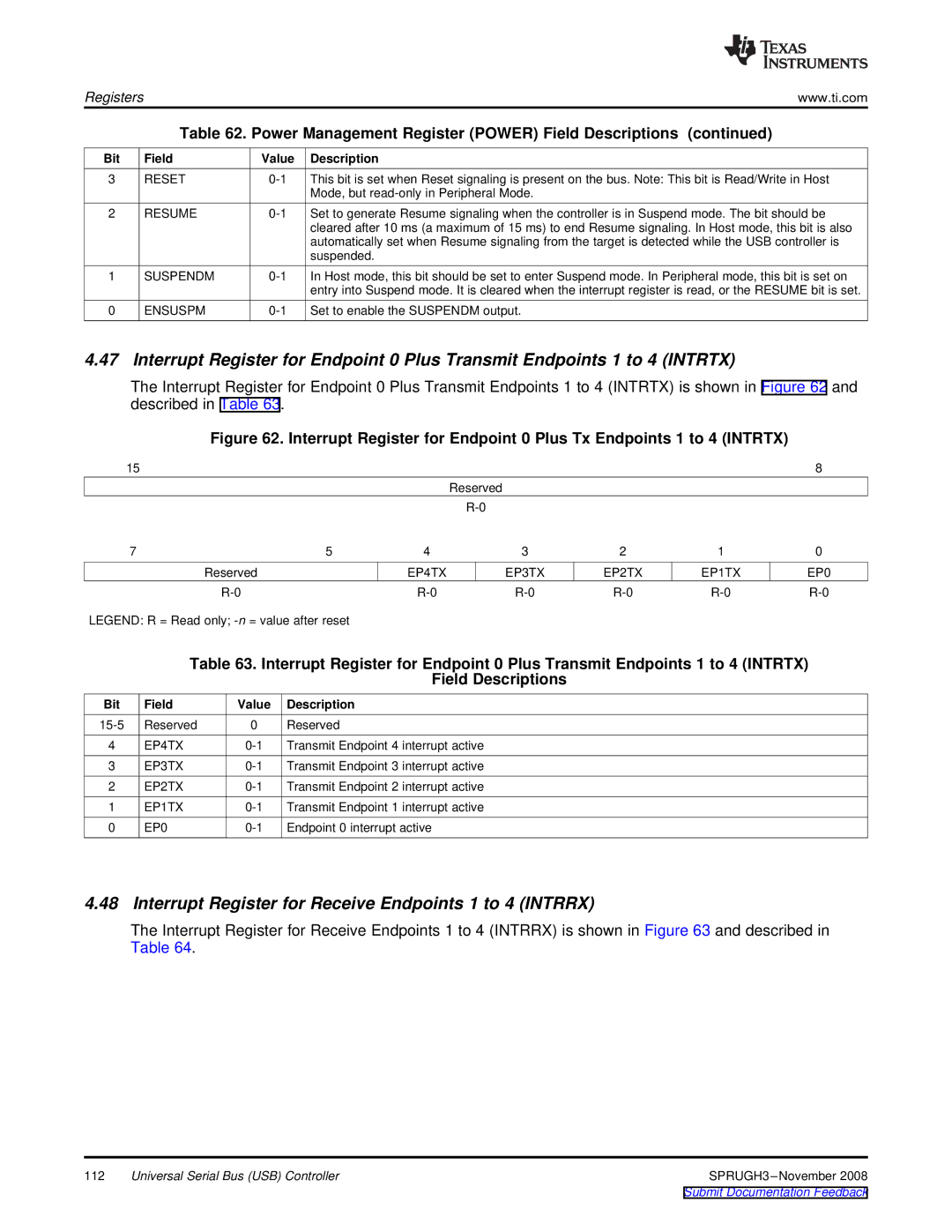
The Interrupt Register for Endpoint 0 Plus Transmit Endpoints 1 to 4 (INTRTX) is shown in Figure 62 and described in Table 63.
Figure 62. Interrupt Register for Endpoint 0 Plus Tx Endpoints 1 to 4 (INTRTX)
| 15 |
|
|
|
|
|
| 8 |
|
|
|
| Reserved |
|
|
|
|
|
|
|
|
|
|
|
| |
| 7 |
| 5 | 4 | 3 | 2 | 1 | 0 |
|
| Reserved |
| EP4TX | EP3TX | EP2TX | EP1TX | EP0 |
|
|
| ||||||
LEGEND: R = Read only; |
|
|
|
|
| |||
| Table 63. Interrupt Register for Endpoint 0 Plus Transmit Endpoints 1 to 4 (INTRTX) | |||||||
|
|
|
| Field Descriptions |
|
|
| |
Bit | Field | Value | Description |
|
|
|
|
|
Reserved | 0 | Reserved |
|
|
|
|
| |
4 | EP4TX | Transmit Endpoint 4 interrupt active |
|
|
|
| ||
3 | EP3TX | Transmit Endpoint 3 interrupt active |
|
|
|
| ||
2 | EP2TX | Transmit Endpoint 2 interrupt active |
|
|
|
| ||
1 | EP1TX | Transmit Endpoint 1 interrupt active |
|
|
|
| ||
0 | EP0 | Endpoint 0 interrupt active |
|
|
|
| ||
4.48 Interrupt Register for Receive Endpoints 1 to 4 (INTRRX)
The Interrupt Register for Receive Endpoints 1 to 4 (INTRRX) is shown in Figure 63 and described in Table 64.
112 | Universal Serial Bus (USB) Controller |