www.ti.com | USB Controller Host and Peripheral Modes Operation |
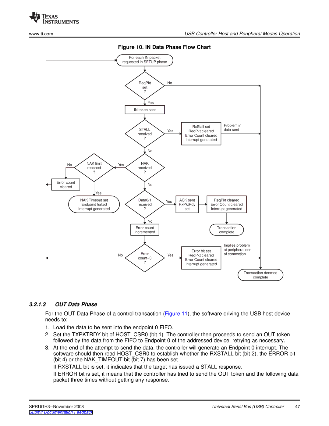
Figure 10. IN Data Phase Flow Chart
For each IN packet
requested in SETUP phase
No | NAK limit | Yes | |
reached | |||
|
| ||
| ? |
|
Error count cleared
Yes
NAK Timeout set
Endpoint halted
Interrupt generated
No
ReqPkt
set
?
![]() Yes
Yes
IN token sent
STALL received
?
![]() No
No
NAK received
?
No
Data0/1 received
?
![]() No
No
Error count incremented
Error
count=3
?
No |
|
|
| |
| RxStall set |
| Problem in | |
Yes |
| data sent | ||
ReqPkt cleared | ||||
| ||||
| Error Count cleared |
| ||
| Interrupt generated |
| ||
Yes | ACK sent | ReqPkt cleared | ||
RxPktRdy | Error Count cleared | |||
| ||||
| set | Interrupt generated | ||
|
| Transaction | ||
|
|
| complete | |
|
|
| Implies problem | |
| Error bit set | at peripheral end | ||
Yes | of connection. | |||
ReqPkt cleared | ||||
| ||||
| Error Count cleared |
| ||
| Interrupt generated |
| ||
|
|
| Transaction deemed | |
|
|
| complete | |
3.2.1.3OUT Data Phase
For the OUT Data Phase of a control transaction (Figure 11), the software driving the USB host device needs to:
1.Load the data to be sent into the endpoint 0 FIFO.
2.Set the TXPKTRDY bit of HOST_CSR0 (bit 1). The controller then proceeds to send an OUT token followed by the data from the FIFO to Endpoint 0 of the addressed device, retrying as necessary.
3.At the end of the attempt to send the data, the controller will generate an Endpoint 0 interrupt. The software should then read HOST_CSR0 to establish whether the RXSTALL bit (bit 2), the ERROR bit (bit 4) or the NAK_TIMEOUT bit (bit 7) has been set.
If RXSTALL bit is set, it indicates that the target has issued a STALL response.
If ERROR bit is set, it means that the controller has tried to send the OUT token and the following data packet three times without getting any response.
Universal Serial Bus (USB) Controller | 47 |