USB Controller Host and Peripheral Modes Operation | www.ti.com |
3.5.4TEST_PACKET
To execute the Test_Packet, the software should:
1.Start a session (if the core is being used in Host mode).
2.Write the standard test packet (shown below) to the Endpoint 0 FIFO.
3.Write 0x8 to the TestMode register to enter Test_Packet test mode.
4.Set the TxPktRdy bit in the CSR0 register (D1).
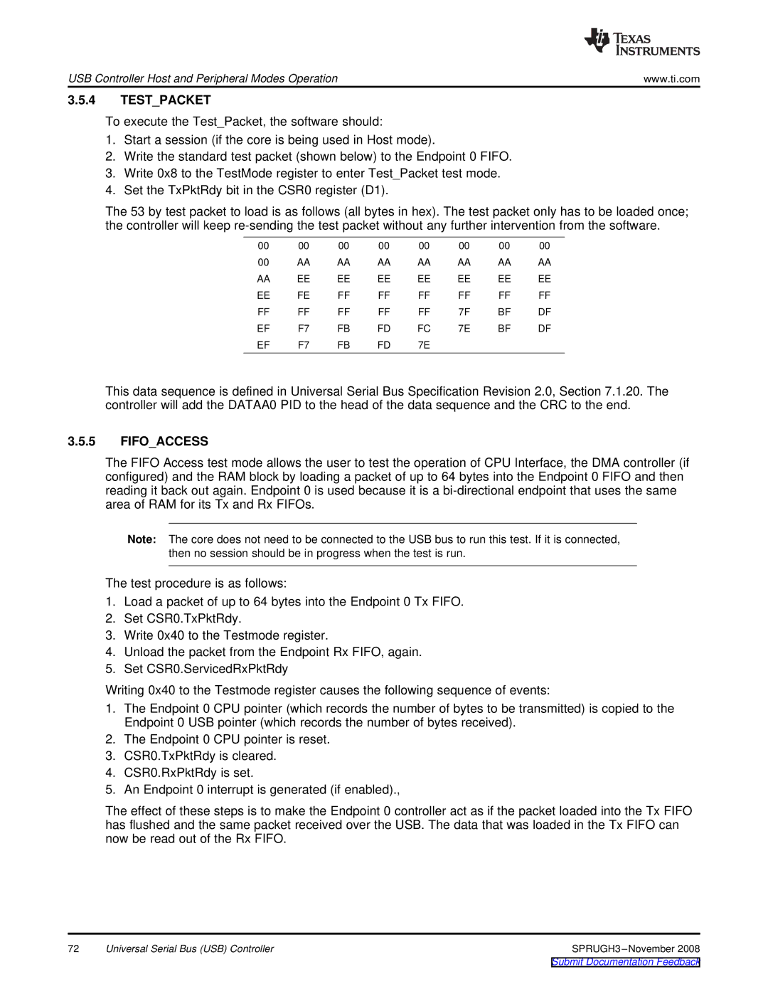
The 53 by test packet to load is as follows (all bytes in hex). The test packet only has to be loaded once; the controller will keep
00 | 00 | 00 | 00 | 00 | 00 | 00 | 00 |
00 | AA | AA | AA | AA | AA | AA | AA |
AA | EE | EE | EE | EE | EE | EE | EE |
EE | FE | FF | FF | FF | FF | FF | FF |
FF | FF | FF | FF | FF | 7F | BF | DF |
EF | F7 | FB | FD | FC | 7E | BF | DF |
EF | F7 | FB | FD | 7E |
|
|
|
This data sequence is defined in Universal Serial Bus Specification Revision 2.0, Section 7.1.20. The controller will add the DATAA0 PID to the head of the data sequence and the CRC to the end.
3.5.5FIFO_ACCESS
The FIFO Access test mode allows the user to test the operation of CPU Interface, the DMA controller (if configured) and the RAM block by loading a packet of up to 64 bytes into the Endpoint 0 FIFO and then reading it back out again. Endpoint 0 is used because it is a
Note: The core does not need to be connected to the USB bus to run this test. If it is connected, then no session should be in progress when the test is run.
The test procedure is as follows:
1.Load a packet of up to 64 bytes into the Endpoint 0 Tx FIFO.
2.Set CSR0.TxPktRdy.
3.Write 0x40 to the Testmode register.
4.Unload the packet from the Endpoint Rx FIFO, again.
5.Set CSR0.ServicedRxPktRdy
Writing 0x40 to the Testmode register causes the following sequence of events:
1.The Endpoint 0 CPU pointer (which records the number of bytes to be transmitted) is copied to the Endpoint 0 USB pointer (which records the number of bytes received).
2.The Endpoint 0 CPU pointer is reset.
3.CSR0.TxPktRdy is cleared.
4.CSR0.RxPktRdy is set.
5.An Endpoint 0 interrupt is generated (if enabled).,
The effect of these steps is to make the Endpoint 0 controller act as if the packet loaded into the Tx FIFO has flushed and the same packet received over the USB. The data that was loaded in the Tx FIFO can now be read out of the Rx FIFO.
72 | Universal Serial Bus (USB) Controller |