www.ti.com | Registers |
4.58 Control Status Register for Endpoint 0 in Host Mode (HOST_CSR0)
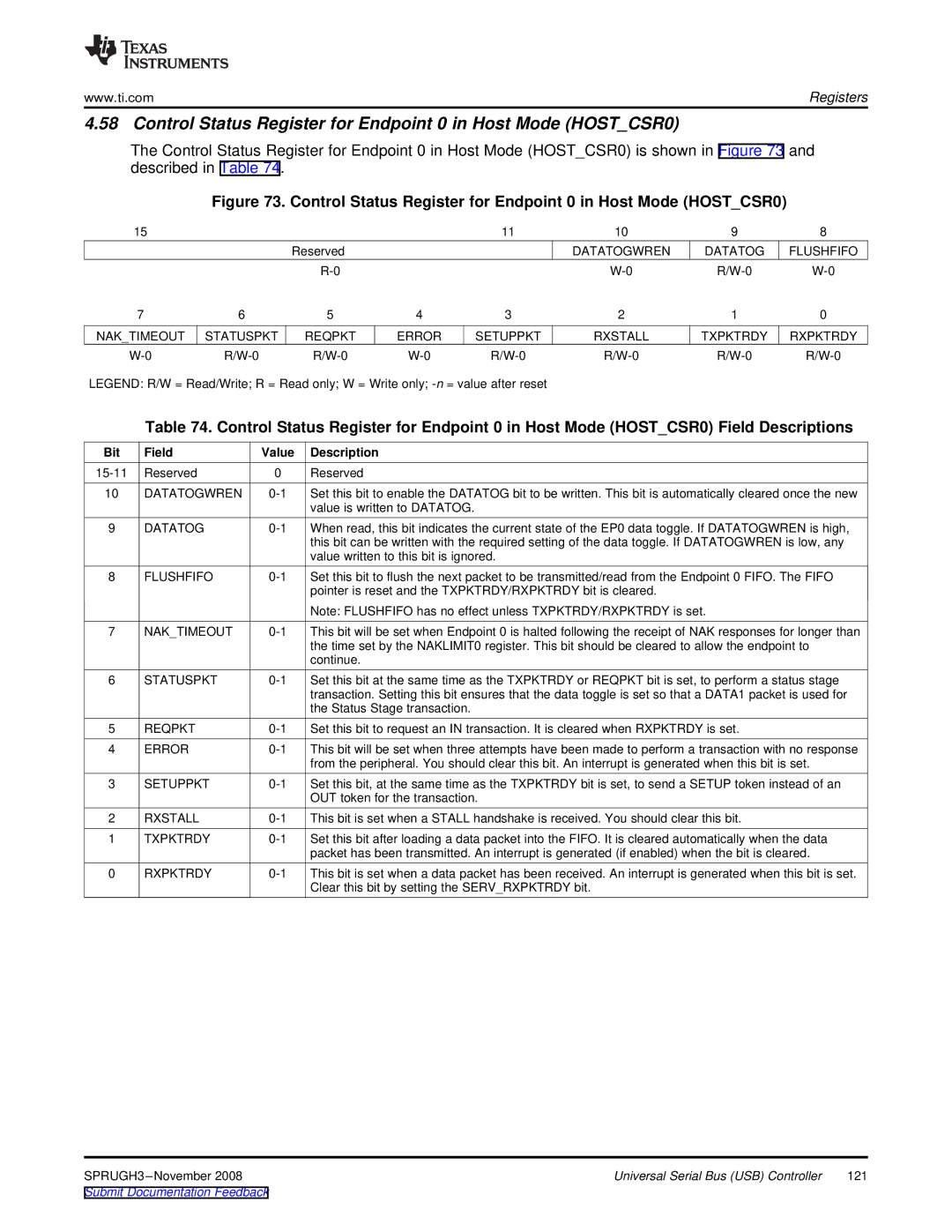
The Control Status Register for Endpoint 0 in Host Mode (HOST_CSR0) is shown in Figure 73 and described in Table 74.
Figure 73. Control Status Register for Endpoint 0 in Host Mode (HOST_CSR0)
15 |
|
|
|
| 11 | 10 | 9 | 8 | |
|
|
| Reserved |
|
| DATATOGWREN | DATATOG | FLUSHFIFO | |
|
|
|
|
|
| ||||
7 |
| 6 |
| 5 | 4 | 3 | 2 | 1 | 0 |
NAK_TIMEOUT | STATUSPKT | REQPKT | ERROR | SETUPPKT | RXSTALL | TXPKTRDY | RXPKTRDY | ||
| |||||||||
LEGEND: R/W = Read/Write; R = Read only; W = Write only; |
|
|
| ||||||
| Table 74. Control Status Register for Endpoint 0 in Host Mode (HOST_CSR0) Field Descriptions | ||||||||
Bit | Field |
| Value | Description |
|
|
|
|
|
Reserved |
| 0 | Reserved |
|
|
|
|
| |
10 | DATATOGWREN | Set this bit to enable the DATATOG bit to be written. This bit is automatically cleared once the new | |||||||
|
|
|
| value is written to DATATOG. |
|
|
|
| |
9 | DATATOG |
| When read, this bit indicates the current state of the EP0 data toggle. If DATATOGWREN is high, | ||||||
|
|
|
| this bit can be written with the required setting of the data toggle. If DATATOGWREN is low, any | |||||
|
|
|
| value written to this bit is ignored. |
|
|
| ||
8 | FLUSHFIFO | Set this bit to flush the next packet to be transmitted/read from the Endpoint 0 FIFO. The FIFO | |||||||
|
|
|
| pointer is reset and the TXPKTRDY/RXPKTRDY bit is cleared. |
|
| |||
|
|
|
| Note: FLUSHFIFO has no effect unless TXPKTRDY/RXPKTRDY is set. |
| ||||
7 | NAK_TIMEOUT | This bit will be set when Endpoint 0 is halted following the receipt of NAK responses for longer than | |||||||
|
|
|
| the time set by the NAKLIMIT0 register. This bit should be cleared to allow the endpoint to | |||||
|
|
|
| continue. |
|
|
|
|
|
6 | STATUSPKT | Set this bit at the same time as the TXPKTRDY or REQPKT bit is set, to perform a status stage | |||||||
|
|
|
| transaction. Setting this bit ensures that the data toggle is set so that a DATA1 packet is used for | |||||
|
|
|
| the Status Stage transaction. |
|
|
|
| |
5 | REQPKT |
| Set this bit to request an IN transaction. It is cleared when RXPKTRDY is set. |
| |||||
4 | ERROR |
| This bit will be set when three attempts have been made to perform a transaction with no response | ||||||
|
|
|
| from the peripheral. You should clear this bit. An interrupt is generated when this bit is set. | |||||
3 | SETUPPKT | Set this bit, at the same time as the TXPKTRDY bit is set, to send a SETUP token instead of an | |||||||
|
|
|
| OUT token for the transaction. |
|
|
| ||
2 | RXSTALL |
| This bit is set when a STALL handshake is received. You should clear this bit. |
| |||||
1 | TXPKTRDY | Set this bit after loading a data packet into the FIFO. It is cleared automatically when the data | |||||||
|
|
|
| packet has been transmitted. An interrupt is generated (if enabled) when the bit is cleared. | |||||
0 | RXPKTRDY | This bit is set when a data packet has been received. An interrupt is generated when this bit is set. | |||||||
|
|
|
| Clear this bit by setting the SERV_RXPKTRDY bit. |
|
| |||
Universal Serial Bus (USB) Controller | 121 | |
Submit Documentation Feedback |
|
|