USB Controller Host and Peripheral Modes Operationwww.ti.com
|
|
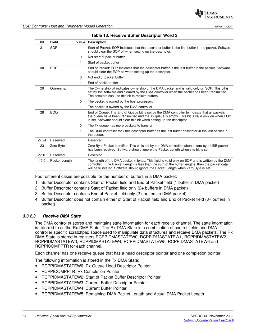
| Table 13. Receive Buffer Descriptor Word 3 |
Bit | Field | Value | Description |
31 | SOP |
| Start of Packet: SOP Indicates that the descriptor buffer is the first buffer in the packet. Software |
|
|
| should clear the SOP bit when setting up the descriptor. |
|
| 0 | Not start of packet buffer |
|
| 1 | Start of packet buffer |
30 | EOP |
| End of Packet: EOP Indicates that the descriptor buffer is the last buffer in the packet. Software |
|
|
| should clear the EOP bit when setting up the descriptor. |
|
| 0 | Not end of packet buffer |
|
| 1 | End of packet buffer |
29 | Ownership |
| The Ownership bit indicates ownership of the DMA packet and is valid only on SOP. This bit is |
|
|
| set by the software and cleared by the DMA controller when the packet has been transmitted. |
|
|
| The software can use this bit to reclaim buffers. |
|
| 0 | The packet is owned by the host processor. |
|
| 1 | The packet is owned by the DMA controller. |
28 | EOQ |
| End of Queue: The End of Queue bit is set by the DMA controller to indicate that all packets in |
|
|
| the queue have been transmitted and the Tx queue is empty. This bit is valid only on when EOP |
|
|
| is set. Software should clear this bit when setting up the descriptor. |
|
| 0 | The Tx queue has more packets to transfer. |
|
| 1 | The DMA controller took this descriptor buffer as the last buffer descriptor in the last packet in |
|
|
| the queue. |
27:24 | Reserved |
| Reserved |
23 | Zero Byte |
| Zero Byte Packet Identifier. This bit is set by the DMA controller when a zero byte USB packet |
|
|
| has been received. Software should ignore the Packet Length when this bit is set. |
22:16 | Reserved |
| Reserved |
15:0 | Packet Length |
| The length of the DMA packet in bytes. This field is valid only on SOP and is written by the DMA |
|
|
| controller. If the Packet Length is less than the sum of the buffer lengths, then the packet data |
|
|
| will be truncated. Software should ignore the Packet Length when Zero Byte is set. |
Four different cases are possible for the number of buffers in a DMA packet:
1.Buffer Descriptor contains Start of Packet field and End of Packet field (1 buffer in DMA packet)
2.Buffer Descriptor contains Start of Packet field only (2+ buffers in DMA packet)
3.Buffer Descriptor contains End of Packet field only (2+ buffers in DMA packet)
4.Buffer Descriptor does not contain either of Start of Packet field and End of Packet field (3+ buffers in packet)
3.3.2.3Receive DMA State
The DMA controller stores and maintains state information for each receive channel. The state information is referred to as the Rx DMA State. The Rx DMA State is a combination of control fields and DMA controller specific scratchpad space used to manipulate data structures and receive DMA packets. The Rx DMA State is stored in registers RCPPIDMASTATEW0, RCPPIDMASTATEW1, RCPPIDMASTATEW2, RCPPIDMASTATEW3, RCPPIDMASTATEW4, RCPPIDMASTATEW5, RCPPIDMASTATEW6 and RCPPICOMPPTR for each channel.
Each channel has one receive queue that has a head descriptor pointer and one completion pointer.
The following information is stored in the Tx DMA State:
∙RCPPIDMASTATEW0: Rx Queue Head Descriptor Pointer
∙RCPPICOMPPTR: Rx Completion Pointer
∙RCPPIDMASTATEW2: Start of Packet Buffer Descriptor Pointer
∙RCPPIDMASTATEW3: Current Buffer Descriptor Pointer
∙RCPPIDMASTATEW4: Current Buffer Pointer
∙RCPPIDMASTATEW5: Remaining DMA Packet Length and Actual DMA Packet Length
64 | Universal Serial Bus (USB) Controller |