www.ti.com | Registers |
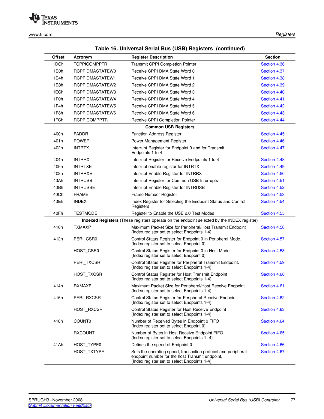
Table 16. Universal Serial Bus (USB) Registers (continued)
Offset | Acronym | Register Description | Section |
1DCh | TCPPICOMPPTR | Transmit CPPI Completion Pointer | Section 4.36 |
1E0h | RCPPIDMASTATEW0 | Receive CPPI DMA State Word 0 | Section 4.37 |
1E4h | RCPPIDMASTATEW1 | Receive CPPI DMA State Word 1 | Section 4.38 |
1E8h | RCPPIDMASTATEW2 | Receive CPPI DMA State Word 2 | Section 4.39 |
1ECh | RCPPIDMASTATEW3 | Receive CPPI DMA State Word 3 | Section 4.40 |
1F0h | RCPPIDMASTATEW4 | Receive CPPI DMA State Word 4 | Section 4.41 |
1F4h | RCPPIDMASTATEW5 | Receive CPPI DMA State Word 5 | Section 4.42 |
1F8h | RCPPIDMASTATEW6 | Receive CPPI DMA State Word 6 | Section 4.43 |
1FCh | RCPPICOMPPTR | Receive CPPI Completion Pointer | Section 4.44 |
|
| Common USB Registers |
|
400h | FADDR | Function Address Register | Section 4.45 |
401h | POWER | Power Management Register | Section 4.46 |
402h | INTRTX | Interrupt Register for Endpoint 0 and for Transmit | Section 4.47 |
|
| Endpoints 1 to 4 |
|
404h | INTRRX | Interrupt Register for Receive Endpoints 1 to 4 | Section 4.48 |
406h | INTRTXE | Interrupt enable register for INTRTX | Section 4.49 |
408h | INTRRXE | Interrupt Enable Register for INTRRX | Section 4.50 |
40Ah | INTRUSB | Interrupt Register for Common USB Interrupts | Section 4.51 |
40Bh | INTRUSBE | Interrupt Enable Register for INTRUSB | Section 4.52 |
40Ch | FRAME | Frame Number Register | Section 4.53 |
40Eh | INDEX | Index Register for Selecting the Endpoint Status and Control | Section 4.54 |
|
| Registers |
|
40Fh | TESTMODE | Register to Enable the USB 2.0 Test Modes | Section 4.55 |
| Indexed Registers (These registers operate on the endpoint selected by the INDEX register) |
| |
410h | TXMAXP | Maximum Packet Size for Peripheral/Host Transmit Endpoint | Section 4.56 |
|
| (Index register set to select Endpoints |
|
412h | PERI_CSR0 | Control Status Register for Endpoint 0 in Peripheral Mode. | Section 4.57 |
|
| (Index register set to select Endpoint 0) |
|
| HOST_CSR0 | Control Status Register for Endpoint 0 in Host Mode | Section 4.58 |
|
| (Index register set to select Endpoint 0) |
|
| PERI_TXCSR | Control Status Register for Peripheral Transmit Endpoint. | Section 4.59 |
|
| (Index register set to select Endpoints |
|
| HOST_TXCSR | Control Status Register for Host Transmit Endpoint | Section 4.60 |
|
| (Index register set to select Endpoints |
|
414h | RXMAXP | Maximum Packet Size for Peripheral/Host Receive Endpoint | Section 4.61 |
|
| (Index register set to select Endpoints |
|
416h | PERI_RXCSR | Control Status Register for Peripheral Receive Endpoint. | Section 4.62 |
|
| (Index register set to select Endpoints |
|
| HOST_RXCSR | Control Status Register for Host Receive Endpoint | Section 4.63 |
|
| (Index register set to select Endpoints |
|
418h | COUNT0 | Number of Received Bytes in Endpoint 0 FIFO | Section 4.64 |
|
| (Index register set to select Endpoint 0) |
|
| RXCOUNT | Number of Bytes in Host Receive Endpoint FIFO | Section 4.65 |
|
| (Index register set to select Endpoints 1- 4) |
|
41Ah | HOST_TYPE0 | Defines the speed of Endpoint 0 | Section 4.66 |
| HOST_TXTYPE | Sets the operating speed, transaction protocol and peripheral | Section 4.67 |
|
| endpoint number for the host Transmit endpoint. |
|
|
| (Index register set to select Endpoints |
|
Universal Serial Bus (USB) Controller | 77 | |
Submit Documentation Feedback |
|
|
