www.ti.com | Registers |
4.25 Receive CPPI Interrupt Enable Clear Register (RCPPIIENCLRR)
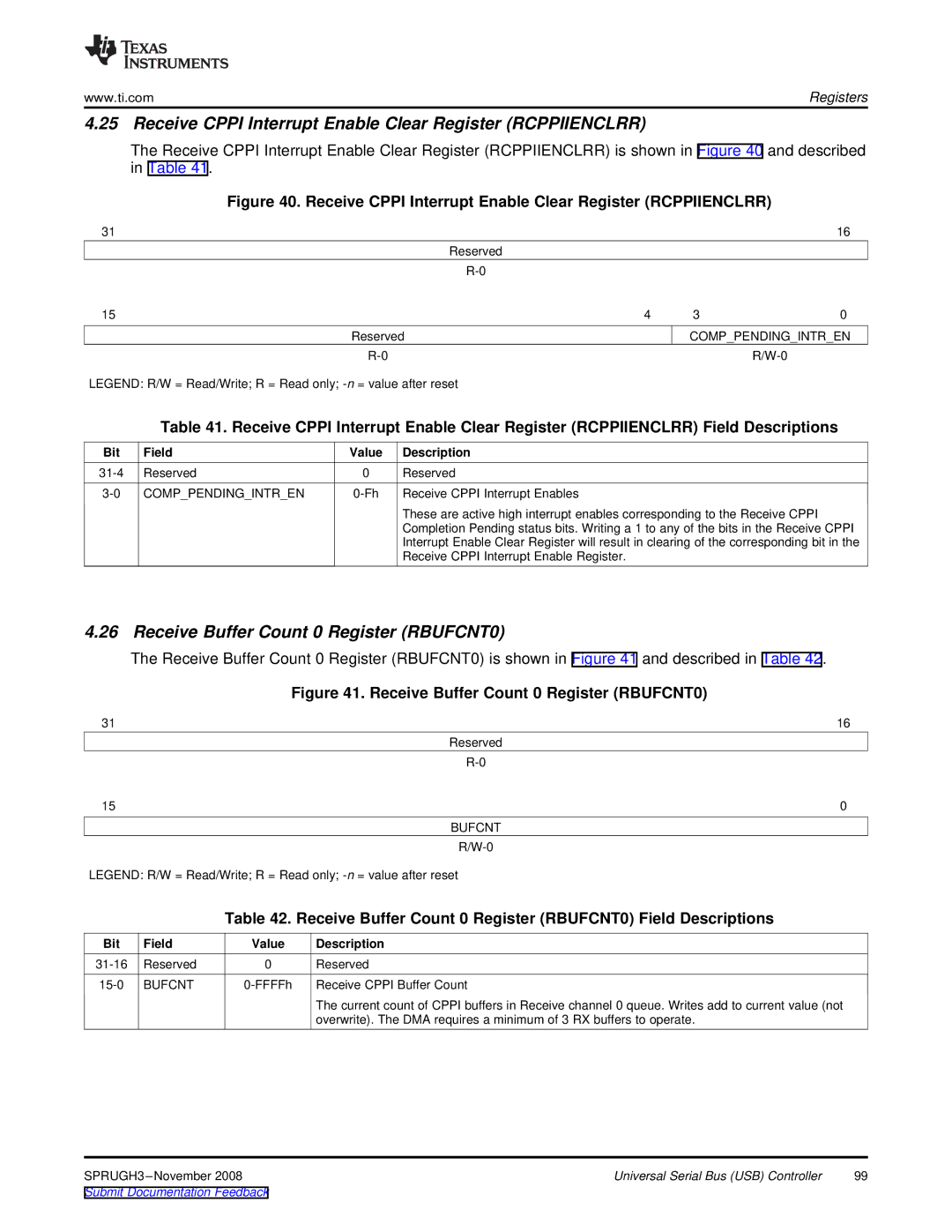
The Receive CPPI Interrupt Enable Clear Register (RCPPIIENCLRR) is shown in Figure 40 and described in Table 41.
Figure 40. Receive CPPI Interrupt Enable Clear Register (RCPPIIENCLRR)
31 |
|
|
|
| 16 |
|
|
| Reserved |
|
|
|
|
|
|
| |
15 |
|
| 4 | 3 | 0 |
|
| Reserved | COMP_PENDING_INTR_EN | ||
|
|
|
| ||
LEGEND: R/W = Read/Write; R = Read only; |
|
| |||
| Table 41. Receive CPPI Interrupt Enable Clear Register (RCPPIIENCLRR) Field Descriptions | ||||
Bit | Field | Value | Description |
|
|
Reserved | 0 | Reserved |
|
| |
COMP_PENDING_INTR_EN | Receive CPPI Interrupt Enables |
|
| ||
|
|
| These are active high interrupt enables corresponding to the Receive CPPI |
| |
|
|
| Completion Pending status bits. Writing a 1 to any of the bits in the Receive CPPI | ||
|
|
| Interrupt Enable Clear Register will result in clearing of the corresponding bit in the | ||
|
|
| Receive CPPI Interrupt Enable Register. |
|
|
4.26 Receive Buffer Count 0 Register (RBUFCNT0)
The Receive Buffer Count 0 Register (RBUFCNT0) is shown in Figure 41 and described in Table 42.
|
| Figure 41. Receive Buffer Count 0 Register (RBUFCNT0) | |
31 |
|
| 16 |
|
|
| Reserved |
|
|
| |
15 |
|
| 0 |
|
|
| BUFCNT |
|
|
| |
LEGEND: R/W = Read/Write; R = Read only; | |||
|
| Table 42. Receive Buffer Count 0 Register (RBUFCNT0) Field Descriptions | |
Bit | Field | Value | Description |
Reserved | 0 | Reserved | |
BUFCNT | Receive CPPI Buffer Count | ||
|
|
| The current count of CPPI buffers in Receive channel 0 queue. Writes add to current value (not |
|
|
| overwrite). The DMA requires a minimum of 3 RX buffers to operate. |
Universal Serial Bus (USB) Controller | 99 | |
Submit Documentation Feedback |
|
|