www.ti.com | Registers |
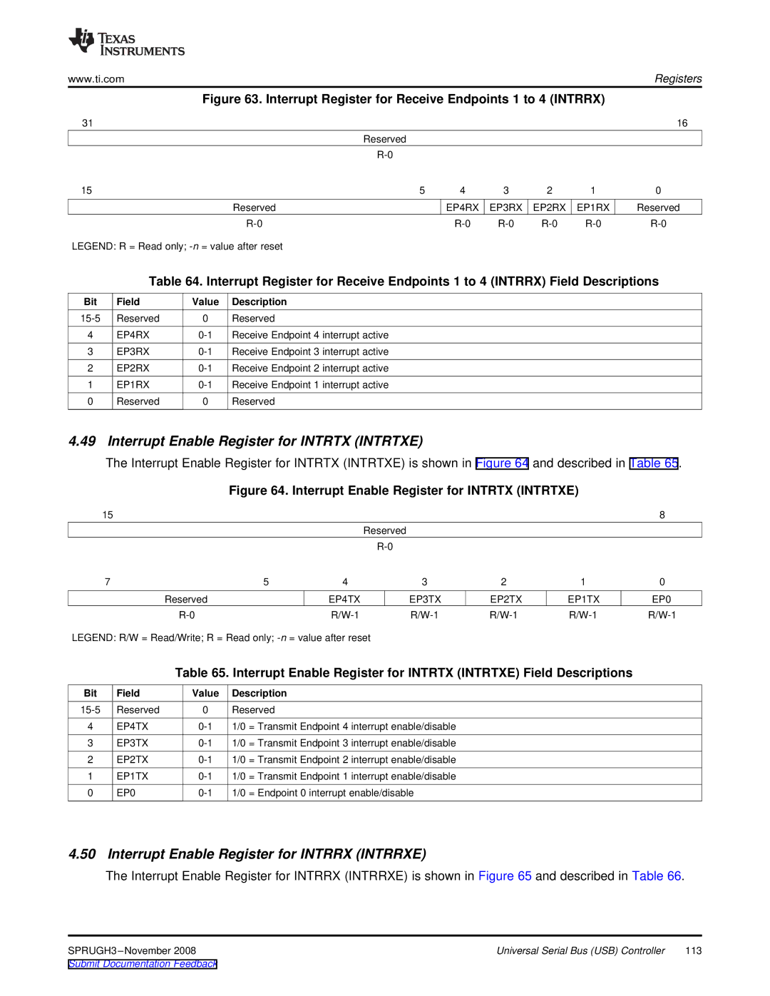
Figure 63. Interrupt Register for Receive Endpoints 1 to 4 (INTRRX)
31 |
|
|
|
|
|
|
| 16 |
|
|
| Reserved |
|
|
|
|
|
|
|
|
|
|
|
|
| |
15 |
|
| 5 | 4 | 3 | 2 | 1 | 0 |
|
|
| Reserved | EP4RX | EP3RX | EP2RX | EP1RX | Reserved |
|
|
| ||||||
LEGEND: R = Read only; |
|
|
|
|
| |||
| Table 64. Interrupt Register for Receive Endpoints 1 to 4 (INTRRX) Field Descriptions | |||||||
Bit | Field | Value | Description |
|
|
|
|
|
Reserved | 0 | Reserved |
|
|
|
|
| |
4 | EP4RX | Receive Endpoint 4 interrupt active |
|
|
|
|
| |
3 | EP3RX | Receive Endpoint 3 interrupt active |
|
|
|
|
| |
2 | EP2RX | Receive Endpoint 2 interrupt active |
|
|
|
|
| |
1 | EP1RX | Receive Endpoint 1 interrupt active |
|
|
|
|
| |
0 | Reserved | 0 | Reserved |
|
|
|
|
|
4.49 Interrupt Enable Register for INTRTX (INTRTXE)
The Interrupt Enable Register for INTRTX (INTRTXE) is shown in Figure 64 and described in Table 65.
Figure 64. Interrupt Enable Register for INTRTX (INTRTXE)
| 15 |
|
|
|
|
|
| 8 |
|
|
|
| Reserved |
|
|
|
|
|
|
|
|
|
|
|
| |
| 7 |
| 5 | 4 | 3 | 2 | 1 | 0 |
|
| Reserved |
| EP4TX | EP3TX | EP2TX | EP1TX | EP0 |
|
|
| ||||||
LEGEND: R/W = Read/Write; R = Read only; |
|
|
|
| ||||
|
| Table 65. Interrupt Enable Register for INTRTX (INTRTXE) Field Descriptions |
| |||||
Bit | Field | Value | Description |
|
|
|
|
|
Reserved | 0 | Reserved |
|
|
|
|
| |
4 | EP4TX | 1/0 = Transmit Endpoint 4 interrupt enable/disable |
|
|
| |||
3 | EP3TX | 1/0 = Transmit Endpoint 3 interrupt enable/disable |
|
|
| |||
2 | EP2TX | 1/0 = Transmit Endpoint 2 interrupt enable/disable |
|
|
| |||
1 | EP1TX | 1/0 = Transmit Endpoint 1 interrupt enable/disable |
|
|
| |||
0 | EP0 | 1/0 = Endpoint 0 interrupt enable/disable |
|
|
| |||
4.50 Interrupt Enable Register for INTRRX (INTRRXE)
The Interrupt Enable Register for INTRRX (INTRRXE) is shown in Figure 65 and described in Table 66.
Universal Serial Bus (USB) Controller | 113 |
