www.ti.com | USB Controller Host and Peripheral Modes Operation |
3.1.1.4Endpoint 0 States
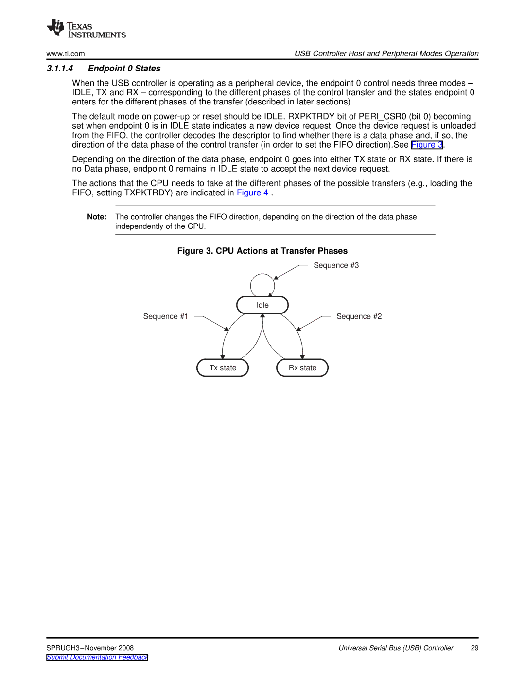
When the USB controller is operating as a peripheral device, the endpoint 0 control needs three modes – IDLE, TX and RX – corresponding to the different phases of the control transfer and the states endpoint 0 enters for the different phases of the transfer (described in later sections).
The default mode on
Depending on the direction of the data phase, endpoint 0 goes into either TX state or RX state. If there is no Data phase, endpoint 0 remains in IDLE state to accept the next device request.
The actions that the CPU needs to take at the different phases of the possible transfers (e.g., loading the FIFO, setting TXPKTRDY) are indicated in Figure 4 .
Note: The controller changes the FIFO direction, depending on the direction of the data phase independently of the CPU.
Figure 3. CPU Actions at Transfer Phases
Sequence #3
Idle
Sequence #1 | Sequence #2 |
Tx state | Rx state |
Universal Serial Bus (USB) Controller | 29 |