Registers | www.ti.com |
4.12 USB End of Interrupt Register (EOIR)
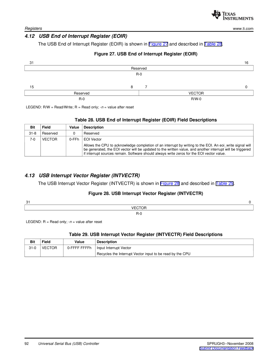
The USB End of Interrupt Register (EOIR) is shown in Figure 27 and described in Table 28.
Figure 27. USB End of Interrupt Register (EOIR)
31 |
|
|
|
| 16 |
|
|
| Reserved |
| |
|
|
|
|
| |
15 |
|
| 8 | 7 | 0 |
|
| Reserved |
| VECTOR | |
|
|
| |||
LEGEND: R/W = Read/Write; R = Read only; |
|
| |||
|
| Table 28. USB End of Interrupt Register (EOIR) Field Descriptions | |||
Bit | Field | Value | Description |
|
|
Reserved | 0 | Reserved |
|
| |
VECTOR | EOI Vector |
|
| ||
Allows the CPU to acknowledge completion of an interrupt by writing to the EOI. An eoi_write signal will be generated, the EOI vector will be updated to the written value, and another interrupt will be triggered if interrupt sources remain. Software should always write zeros for the EOI vector value.
4.13 USB Interrupt Vector Register (INTVECTR)
The USB Interrupt Vector Register (INTVECTR) is shown in Figure 28 and described in Table 29.
Figure 28. USB Interrupt Vector Register (INTVECTR)
31 | 0 |
VECTOR
LEGEND: R = Read only;
Table 29. USB Interrupt Vector Register (INTVECTR) Field Descriptions
Bit | Field | Value | Description |
VECTOR | Input Interrupt Vector | ||
|
|
| Recycles the Interrupt Vector input to be read by the CPU |
92 | Universal Serial Bus (USB) Controller |