www.ti.comRegisters
Table 60. Receive CPPI Completion Pointer (RCPPICOMPPTR) Field Descriptions (continued)
Bit | Field | Value | Description |
0 | RDBK_MODE |
| Readback / Compare Mode |
0Compare Mode. Indicates that the value that is presented on bits 31:2 of the read data should be compared against the value that is currently contained in bits 31:2 of this location. If the two match, the interrupt bit corresponding to this Receive Queue should be deasserted.
1Readback Mode. Indicates that the value that is presented on bits 31:2 of the read data should be read from this location and the interrupt for this Receive Queue should be asserted. This bit is read as zero.
4.45Function Address Register (FADDR)
The Function Address Register (FADDR) is shown in Figure 60 and described in Table 61.
|
| Figure 60. Function Address Register (FADDR) |
7 | 6 | 0 |
Reserved |
| FUNCADDR |
|
LEGEND: R/W = Read/Write;
Table 61. Function Address Register (FADDR) Field Descriptions
Bit | Field | Value | Description |
7 | Reserved | 0 | Reserved |
FUNCADDR | |||
|
|
| When used in Peripheral mode (DevCtl.D2=0), this register should be written with the address |
|
|
| received through a SET_ADDRESS command, which will then be used for decoding the function |
|
|
| address in subsequent token packets. |
When used in Host mode (DevCtl.D2=1), this register should be set to the value sent in a
SET_ADDRESS command during device enumeration as the address for the peripheral device.
4.46 Power Management Register (POWER)
The Power Management Register (POWER) is shown in Figure 61 and described in Table 62.
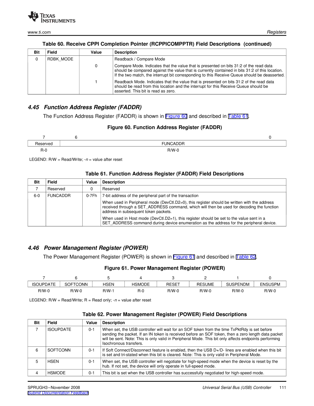
Figure 61. Power Management Register (POWER)
7 | 6 | 5 | 4 | 3 | 2 | 1 | 0 |
ISOUPDATE | SOFTCONN | HSEN | HSMODE | RESET | RESUME | SUSPENDM | ENSUSPM |
LEGEND: R/W = Read/Write; R = Read only;
Table 62. Power Management Register (POWER) Field Descriptions
Bit | Field | Value | Description |
|
7 | ISOUPDATE | When set, the USB controller will wait for an SOF token from the time TxPktRdy is set before |
| |
|
|
| sending the packet. If an IN token is received before an SOF token, then a zero length data packet | |
|
|
| will be sent. Note: This is only valid in Peripheral Mode. This bit only affects endpoints performing | |
|
|
| Isochronous transfers. |
|
6 | SOFTCONN | If Soft Connect/Disconnect feature is enabled, then the USB D+/D- lines are enabled when this bit | ||
|
|
| is set and |
|
5 | HSEN | When set, the USB controller will negotiate for |
| |
|
|
| hub. If not set, the device will only operate in |
|
4 | HSMODE | This bit is set when the USB controller has successfully negotiated for |
| |
| Universal Serial Bus (USB) Controller | 111 | ||
Submit Documentation Feedback |
|
| ||