Registers |
|
| www.ti.com |
| Table 87. Receive Interval Register (Host mode only) (HOST_RXINTERVAL) Field Descriptions | ||
Bit | Field | Value | Description |
POLINTVL_NAKLIMIT | For Interrupt and Isochronous transfers, defines the polling interval for the | ||
|
|
| |
|
|
| frames/microframes after which the endpoint should timeout on receiving a stream of NAK |
|
|
| responses. There is a transmit Interval register for each configured transmit endpoint |
|
|
| (except Endpoint 0). In each case the value that is set defines a number of |
|
|
| frames/microframes (High Speed transfers), as follows: |
Transfer Type Speed Valid values (m) Interpretation
Interrupt Low Speed or Full Speed 1 - 255 Polling interval is m frames
High Speed 1 - 16 Polling interval is
Isochronous Full Speed or High Speed 1 - 16 Polling interval is
Bulk Full Speed or High Speed 2 - 16 NAK Limit is
Note: A value of 0 or 1 disables the NAK timeout function
4.72 Configuration Data Register (CONFIGDATA)
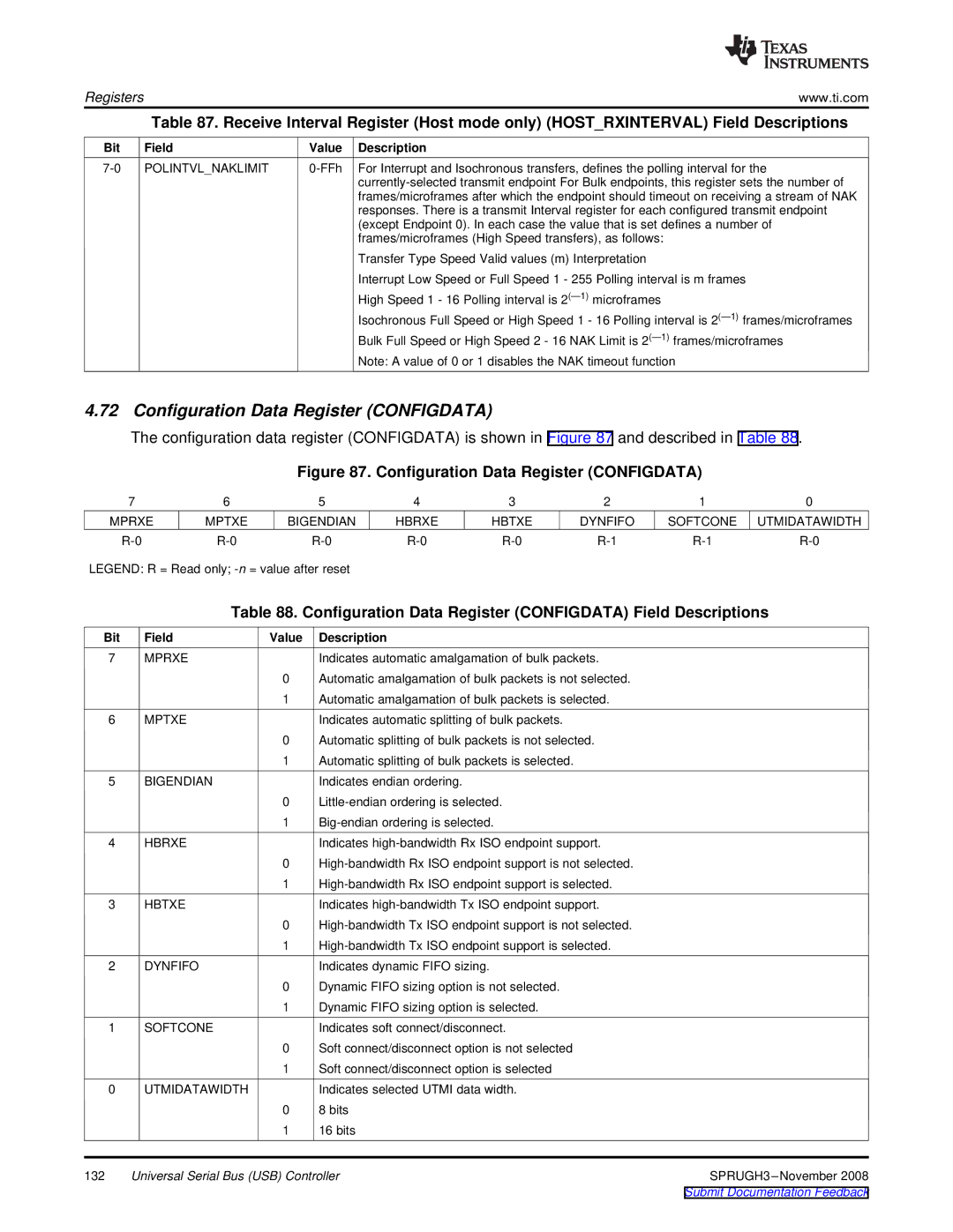
The configuration data register (CONFIGDATA) is shown in Figure 87 and described in Table 88.
Figure 87. Configuration Data Register (CONFIGDATA)
7 | 6 | 5 | 4 | 3 | 2 | 1 | 0 |
MPRXE | MPTXE | BIGENDIAN | HBRXE | HBTXE | DYNFIFO | SOFTCONE | UTMIDATAWIDTH |
LEGEND: R = Read only;
Table 88. Configuration Data Register (CONFIGDATA) Field Descriptions
Bit | Field | Value | Description |
|
7 | MPRXE |
| Indicates automatic amalgamation of bulk packets. |
|
|
| 0 | Automatic amalgamation of bulk packets is not selected. |
|
|
| 1 | Automatic amalgamation of bulk packets is selected. |
|
6 | MPTXE |
| Indicates automatic splitting of bulk packets. |
|
|
| 0 | Automatic splitting of bulk packets is not selected. |
|
|
| 1 | Automatic splitting of bulk packets is selected. |
|
5 | BIGENDIAN |
| Indicates endian ordering. |
|
|
| 0 |
| |
|
| 1 |
| |
4 | HBRXE |
| Indicates |
|
|
| 0 |
| |
|
| 1 |
| |
3 | HBTXE |
| Indicates |
|
|
| 0 |
| |
|
| 1 |
| |
2 | DYNFIFO |
| Indicates dynamic FIFO sizing. |
|
|
| 0 | Dynamic FIFO sizing option is not selected. |
|
|
| 1 | Dynamic FIFO sizing option is selected. |
|
1 | SOFTCONE |
| Indicates soft connect/disconnect. |
|
|
| 0 | Soft connect/disconnect option is not selected |
|
|
| 1 | Soft connect/disconnect option is selected |
|
0 | UTMIDATAWIDTH |
| Indicates selected UTMI data width. |
|
|
| 0 | 8 bits |
|
|
| 1 | 16 bits |
|
132 | Universal Serial Bus (USB) Controller | |||
|
|
|
| Submit Documentation Feedback |