Srcp
Page
General Contents
Parameters
Iii
Communication with PC 11-1
Appendix 16-1
Memo
Overview
Chapter
Features of the Srcp Series Controller
Basic steps
Setting Up for Operation
Srcp controller
External View and Part Names
Exterior of the Srcp controller SRCP-05 SRCP-05A, 10A, 20A
Three-side view of the Srcp controller
2 TPB
System configuration
System Configuration
Accessories and Options
Accessories
Peripheral options
Memo
Installation and Connection
Installing the Srcp Controller
Installation method
Installation location
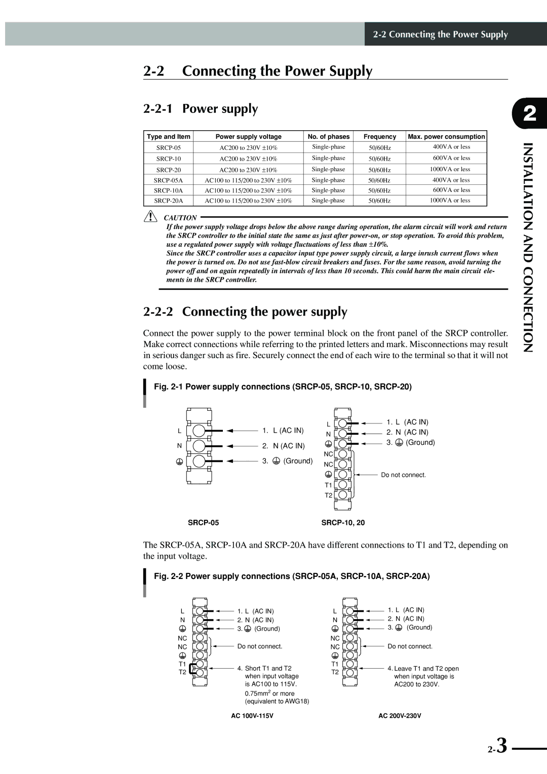
Connecting the Power Supply
Power supply
Connecting the power supply
Installing a circuit protector
Installing an external leakage breaker
Installing current control switches
Connecting the Srcp to the Control Unit
Grounding
Insulation resistance and voltage breakdown tests
Robot I/O connector and signal table
Connecting to the Robot
Connecting to the I/O. CN Connector
Slotted screwdriver Terminal numbers are not actually
Connecting to the EXT. CN Connector
Connecting the Srcp controller to a regenerative unit
Connecting to the Regenerative Unit
Memo
Interface
I/O Signals
1 I/O. CN connector signals
2 EXT. CN connector signals
Dedicated command input
Input Signal Description
Relative point movement command INC-PT
Absolute point movement command ABS-PT
Automatic operation start command AUTO-R
Step operation start command STEP-R
Return-to-origin command ORG-S
Servo recovery command Servo
Reset command Reset
PRM7
General-purpose input DI0 to DI7
Service mode input Svce
Interlock Lock
Emergency stop inputs 1, 2 EMG1, EMG2
Command-in-progress output Busy
Output Signal Description
Dedicated output
Ready-to-operate output Ready
Feedback pulse output PA±, PB±, PZ±, PZM±
General-purpose output DO0 to DO4
I/O Circuits
1 I/O circuit specifications
Circuit and connection example
2 I/O circuit and connection example
Connection to PLC output unit
I/O Connection Diagram
Connection to the Mitsubishi PLC AX41 input unit
Connection to PLC input unit
When turning the power on
I/O Control Timing Charts
When executing a dedicated input command
30ms or less 1ms or less 1ms or less 1ms or less
3When a command cannot be executed from the beginning
4When command execution cannot be completed
When interlock signal is input
When alarm is issued
When emergency stop is input
When executing a point movement command
Basic Operation of the TPB
Connecting the TPB to the Srcp controller
Connecting and Disconnecting the TPB
When the power supply to the controller is turned off
When the power supply to the controller is turned on
Disconnecting the TPB from the Srcp controller
Basic Operation of the TPB
Basic Key Operation
Program execution screen
Reading the Screen
Program edit screen
1MOD 2INS 3DEL 4CHG
Point edit screen teaching playback
DIO monitor screen
CHG SPD
PGM
Hierarchical Menu Structure
Explanation of access level
Restricting Key Operation by Access Level
Memory card
Changing an access level
1EDIT2OPRT3SYS 4CARD
Parameters
Parameters
Setting the Parameters
PRM0 Robot type number
Parameter Description
PRM1 + soft limit
PRM2 soft limit
PRM4 Acceleration
PRM3 Payload
PRM5 Return-to-origin direction
PRM6 Positioning-completed pulse
PRM8 No. of conditional input points
PRM7 I/O point movement command speed
PRM9 Movf speed
PRM10 Return-to-origin speed
PRM12 Lead length
PRM11 No. of encoder pulses 4 mode
PRM13 Origin detection method
PRM14 Overload current
PRM19 Position proportional gain
PRM18 Speed integration gain
PRM20 OUT valid position
PRM21 Position data unit
PRM25 Not used
PRM24 Teaching count data TPB entry
PRM26 Teaching movement data
PRM27 Teaching movement data 1 for TPB
PRM33 Operation at return-to-origin complete
PRM32 Alarm number output
Bit 1 Ready signal sequence setting
PRM34 System mode selection
Bit 3 Voltage check setting for system backup battery
Bit 6 Interlock function setting
PRM39 Control mode selection
PRM38 Speed delay compensation gain
PRM40 Reset execution condition selection
PRM35 Origin shift
PRM42 I/O point movement command speed
PRM41 I/O point movement command speed
PRM43 I/O point movement command speed
PRM44 Maximum speed setting
PRM46 Servo status output
PRM47 Communication parameter setting
PRM48 Pre-operation action selection
PRM49 Controller version
PRM51 Lead program number
PRM52 Hold gain
PRM53 Zone output selection
Zone output function
Zone setting range and output port
PRM55 Magnetic pole position
PRM54 Magnetic pole detection level
PRM56 Controller version
PRM58 Not used
Programming
Basic Contents
Editing Programs
1EDIT2OPRT3SYS 4MON
Creating programs after initialization
1PGM 2PNT 3UTL
EDIT-PGM
001MOVA 100 Point No0→999
1MOD 2INS 3DEL 4CHG EDIT-PGM
Creating a new program
PGM PNT UTL EDIT-PGM
Adding a step
EDIT-PGM No10 051JMPF 10 ,31 ,5
MOD INS DEL CHG
Correcting a step
Mova
Movf
1MOD 2INS 3DEL 4CHG
Inserting a step
MOD INS EDIT-PGM
Deleting a step
Copying a program
Program Utility
Deleting a program
Viewing the program information
1COPY2DEL 3LIST
EDIT-UTL
Editing Point Data
Menu
Manual Data Input
1MDI 2TCH 3DTCH4DEL
EDIT-PNT-MDI
Teaching Playback
EDIT-PNT-TCH1100 P500 = 167.24 mm 167.24 1CHG 2SPD3SSET4next
Direct Teaching
EDIT-PNT-DTCH
TRC
Manual Control of General-Purpose Output
EDIT-PNT-DTCH
Manual Release of Holding Brake
1CHG 2DO 3BRK EDIT-PNT-DTCH
1CHG 2DO 3BRK
Deleting Point Data
Tracing Points Moving to a registered data point
Robot Language
Jmpf
Robot Language Table
Robot Language Syntax Rules
Command statement format
Point variable P
Variables
Counter array variable C, Counter variable D
Flag variable memory input/output 100 to
Multi-task function
Program Function
Robot Language Description
Mova
Movi
Movf
4 JMP
Other
Jmpf
7 L
Jmpb
9 do
Call
Timr
Wait
13 P+
12 P
14 P
Format Example Explanation
Srvo
Stop
Others
Return-to-origin must be reperformed in this case
Orgn
Toff
18 TON
Condition is met
Jmpp
Fined
21 MAT
Msel
Robot
Movm
Jmpd
Jmpc
27 C
Csel
29 C
28 C+
30 D
31 D+
Shft
32 D
Sample Programs
Moving between two points
Moving at an equal pitch
Cancels job 1 command
Program Comment NO1
Point
Program Comment NO1 Main routine
Switching the program from I/O
Parameter
Program description
NO2
Axis movement and I/O multi-task
Turns DO0 off
When P1 is nearer to the plus side than P0
Memo
Operating the Robot
1ORG 2STEP3AUTO
Performing Return-to-Origin
Robot
Using Step Operation
OPRT- 010 001MOVA 999,50
SPD
OPRT-AUTO 100 0 0 001MOVA 254,100
Using Automatic Operation
Therobot
Switching the Execution Program
Recovering from an emergency stop
Emergency Stop Function
Initiating an emergency stop
Robot
Displaying the Memory I/O Status
Oprt
Displaying the Variables
Memo
Other Operations
1PGM 2PNT 3PRM 4ALL
Initialization
10-3
Display from the monitor menu
DIO Monitor Display
1DIO 2DUTY
MON-DIO
Display from the DIO key operation
System Information Display
OPRT-AUTO
1EDIT2OPRT3SYS 4MON Information
Service mode function
Safety settings for Service mode
Limiting command input from any device other than TPB
Limiting the robot movement speed
Hold-to-run function
Prohibiting the automatic operation and step operation
1ACLV2SVCE
Enabling/disabling the Service mode function
SYS-SAFE-SVCE-SET
Service mode = 0Invalid 1Valid
Setting the Service mode functions
1SAVE2CHG 3CANCEL
Viewing hidden parameters
System utilities
Saving controller data to a memory card
Using a Memory Card
1SAVE2LOAD3FMT 4ID
UP-ID
UP-SAVEAREA
UP-SAVE
Area UP-ID
Loading data from a memory card
UP-LOADAREA 3 Select menu
SYS-B.UP
Formatting a memory card
1SAVE2LOAD3FMT 4ID UP-ID
Viewing the ID number for memory card data
Method
Duty load factor monitor
10-21
Menu
Measuring the duty load factor
1Manual load using the TPB or Popcom options
Using the internal flash ROM
2Auto loading at Srcp power-on Auto-load function
Saving the parameter data to the flash ROM
FROM-SAVE
Saving the parameter data onto the flash ROM
1ALOD
FROM-SAVE
Operations
Manually loading the data from flash ROM
10-27
FROM-INIT
Initializing the flash ROM data
SYS-B.UP-FROM from
10-30
Communication with PC
PRM47 settings default value
Communication Parameter Specifications
Connector model
Communication Cable Specifications
Connector model controller side
Connector model computer side
Communication Command Specifications
Robot movement
Communication Command List
11-6
11-7
Robot movements
Communication Command Description
@ORG
Transmission example
@SRUN
@RUN
@SRVO servo status
Servo status
@XINC, @XDEC
@X+, @X
@MOVD X-axis position mm,speed
Axis position
@MOVA point number,speed
Point number
10@MOVI point number,speed
14@TIMR time
11@MOVF point number,DI number,DI status
15@P point number
16@P+
17@P
20@MSEL pallet number
18@MOVM pallet work position,speed
22@C counter value
21@CSEL array element number
23@C+ addition value
24@C- subtraction value
26@D+ addition value
27@D- subtraction value
28@SHFT point number
Data handling
@?MEM
@?STP program number
@?VER
@?ROBOT
History number
11 @?ALM history number,display count
Display count
12@?ERR history number,display count
14@?SRVO
13@?EMG
15@?ORG
16@?MODE
17@?PVA
18@?DI general-purpose input or memory input number
19@?DO general-purpose output or memory output number
Parameter number
20-1 @?PRM parameter number
20-2 @?PRM parameter number,parameter number
21-1 @?P point number
22-1 @READ program number,step number,number of steps
21-2 @?P point number,point number
Step number
Number of steps
22-3 @READ PNT
22-4 @READ PRM
22-5 @READ ALL
22-7 @READ MIO
22-6 @READ DIO
22-8 @READ INF
23-1 @WRITE PGM
23-3 @WRITE PRM
23-2 @WRITE PNT
23-4 @WRITE ALL
24@?MAT pallet number
25@?MSEL
27@?C array element number
26@?CSEL
Element number
28@?D
Utilities
@SWITSK task number
@SWI program number
Task number
@SINS program number,step number
@SMOD program number,step number
@SDEL program number,step number
@DEL program number
@PDEL point number,number of points
Number of points
Message Tables
Error Messages
Error message specifications
Command error message
Message Soft limit over Cause
Operation error message
Program error message
Multi-task error message
System error message
TPB Error Messages
Message specifications
Stop Messages
Stop messages
Displaying the Error History
1ALM 2ERR
12-10
Troubleshooting
If a Trouble Occurs
What you were using
Alarm specifications
Alarm and Countermeasures
If an alarm is issued
To cancel the alarm
Alarm Message Meaning Possible Cause Action
Alarm message list
13-5
13-6
Relating to the robot movement
Troubleshooting for Specific Symptom
Troubleshooting for Specific Symptom
Relating to the I/O
TPB
Other
Displaying the Alarm History
13-12
Maintenance and Warranty
Warranty description
Warranty
Warranty Period
Exceptions to the Warranty
Battery product number CR2450THE Toshiba Battery
Replacing the System Backup Battery
Updating the System
Specifications
Srcp sereis
Basic specifications
LED display
Robot number list
TPB
15-2 TPB
Regenerative Unit RGU-2
15-6
Appendix
Using the memory card
How to Handle Options
Precautions when using the memory card
Memory card
Data size that can be saved
When the PC has a D-sub 25-pin connector
When the PC has a D-sub 9-pin connector
Popcom communication cable
Memo
Revision record