HARDWARE DESIGN
The hysteresis specified in the 8284A data | to switch at specified LOW and HIGH vol- | |||
sheet implies that at least 0.25 volts will | tages (VIL and VIH), but the actual switching | |||
separate the logic 0 and I switching point of | point is anywhere in between. | |||
the 8284A reset input. Inputs without hys- | Since VIL min. is specified at 0.8 volts, the | |||
teresis switch from LOW to HIGH and | ||||
hysteresis guarantees that the reset will be | ||||
HIGH to LOW at approximately the same | ||||
active until the input reaches at least 1.05 | ||||
voltage threshold. The inputs are guaranteed | ||||
volts. A reset will not be recognized until the | ||||
|
|
| ||
|
|
| input drops at least 0.25 volts below the reset | |
SIGNAL | : | CONDITION | inputs VIH of 2.6 volts. | |
|
| To guarantee reset from power up, the reset | ||
| FLOAT | input must remain below 1.05 volts for 50 p,s | ||
* |
| |||
|
| after Vee has reached the minimum supply | ||
|
|
| ||
SSO |
|
| voltage of 4.5 volts. The hysteresis allows the | |
|
| reset input to be driven by a simple RC cir- | ||
* |
|
| ||
101M |
|
| cuit (Fig. | |
* |
|
| The calculated RC value does not include | |
DT/R |
|
| ||
* |
| DRIVEN HIGH, | time for the power supply to reach 4.5 volts, | |
DEN |
| |||
| THEN FLOAT | or the charge accumulated during this inter- | ||
* |
| |||
|
| |||
WR |
|
| val. Without the hysteresis, the reset output | |
* |
|
| ||
|
| might oscillate as the input voltage passes | ||
RD |
|
| ||
* |
|
| through the switching voltage of the input. | |
INTA |
|
| ||
|
| The calculated RC value provides the min- | ||
|
|
| ||
ALE |
|
| imum required reset period of 50 p,s for | |
| LOW | 8284A's that switch at the 1.05 volt level, and | ||
* |
| |||
HLDA |
|
| a reset period of approximately 162 p,s for | |
|
|
| ||
Figure | 8284A's that switch at the 2.6 volt level. | |||
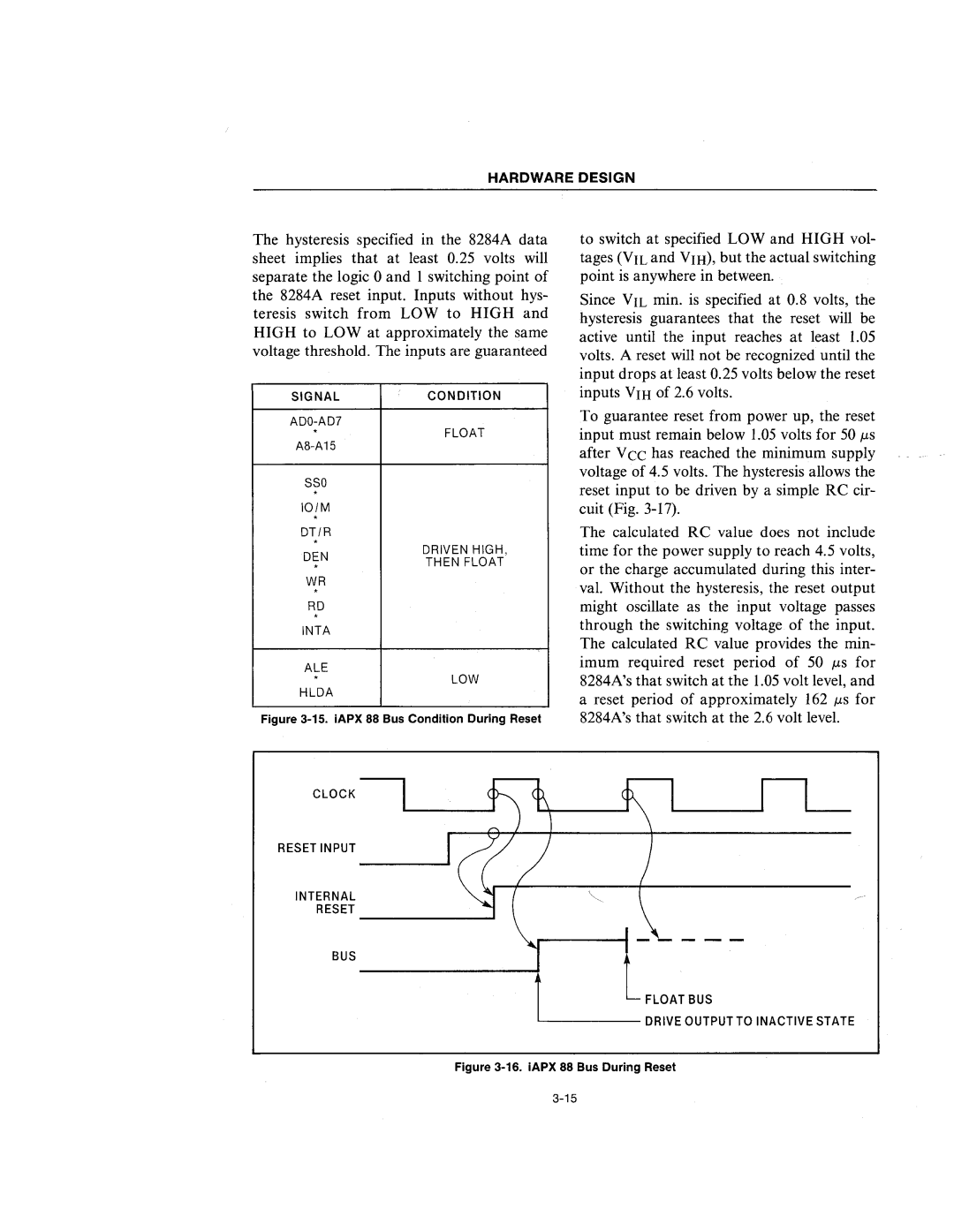
CLOCK
RESET INPUT
iNTERNAL
RESET _______...1
r
BUS
FLOAT BUS
L