INTRODUCTION
The 8088 instructions can be from one byte to seven bytes in length, depending on the number of operands and immediate data fields included in the instruction. Great care has been taken in the design of the instruc- tion set to allow for efficient programs to be written. The 8088 instructions need not be word aligned (starting at even addresses) con- trary to many other
The 8088 instruction set also has been designed such that some registers are always used for certain functions. The CX register, for example, is used for a count value by some repetitive instructions. This implied use of registers allows shorter programs because the register address need not be contained in those instructions.
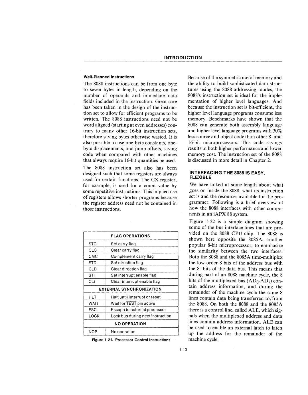
| FLAG OPERATIONS |
STC | Set carry flag |
CLC | Clear carry flag |
CMC | Complement carry flag |
STD | Set direction flag |
CLD | Clear direction flag |
STI | Set interrupt enable flag |
CLI | Clear interrupt enable flag |
EXTERNAL SYNCHRONIZATION | |
HLT | Halt until interrupt or reset |
WAIT | Wait for TEST pin active |
ESC | Escape to external processor |
LOCK | Lock bus during next instruction |
| NO OPERATION |
NOP | No operation |
Figure 1-21. Processor Control Instructions
Because of the symmetric use of memory and the ability to build sophisticated data struc- tures using the 8088 addressing modes, the 8088's instruction set is ideal for the imple- mentation of higher level languages. And because the instruction set is
INTERFACING THE 8088 IS EASY,
FLEXIBLE
We have talked at some length about what goes on inside the 8088, what its instruction set is and the resources available for the pro- grammer. Following is a brief overview of how the 8088 interfaces with other compo- nents in an iAPX 88 system.