HARDWARE DESIGN
are always met by the 8284A's RDY and AEN inputs. If this can not be guaranteed, the asynchronous configuration must be used.
Asynchronous System
To insert a wait state in the asynchronous configuration, the RDY inputs must be valid at least 35ns before the rising edge of the clock in state T2. The AEN must be valid 50ns before that edge.
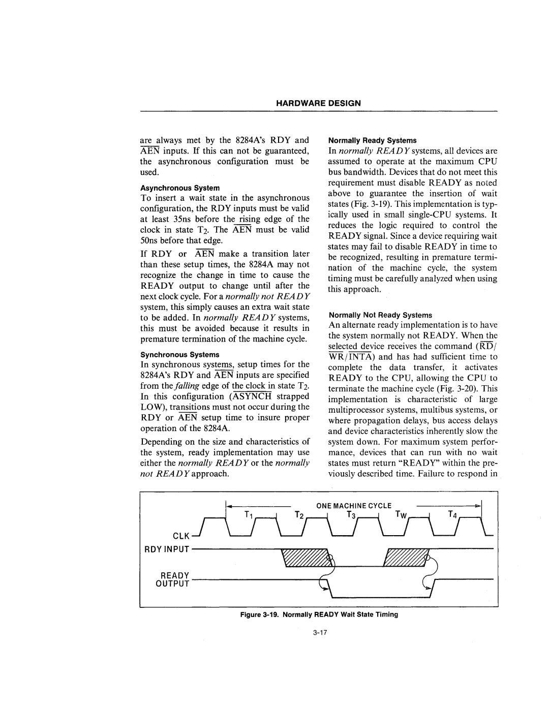
If RDY or AEN make a transition later than these setup times, the 8284A may not recognize the change in time to cause the READY output to change until after the next clock cycle. For a normally not READY system, this simply causes an extra wait state to be added. In normally READY systems, this must be avoided because it results in premature termination of the machine cycle.
Synchronous Systems
In synchronous systems, setup times for the 8284A's RDY and AEN inputs are specified from the falling edge of the clock in state T2. In this configuration (ASYNCH strapped LOW), transitions must not occur during the RDY or AEN setup time to insure proper operation of the 8284A.
Depending on the size and characteristics of the system, ready implementation may use either the normally READY or the normally not READ Y approach.
Normally Ready Systems
In normally READ Y systems, all devices are assumed to operate at the maximum CPU bus bandwidth. Devices that do not meet this requirement must disable READY as noted above to guarantee the insertion of wait states (Fig.
Normally Not Ready Systems
An alternate ready implementation is to have the system normally not READY. When the selected device receives the command (RD j WRjINTA) and has had sufficient time to complete the data transfer, it activates READY to the CPU, allowing the CPU to terminate the machine cycle (Fig.
