ARCHITECTURE AND INSTRUCTIONS
The ASSUME statement on line 2 complies with the following rule:
at the very beginning ofany segment contain- ing code, we must tell the assembler what to assume is in the CS register when that code is
executed. This will always be the starting address, without the last four "0" bits of the segment, so we must include the statement:
ASSUME CS: Name_oLsegment
Now consider a more detailed
the segment is SUM, defined to be a byte (DB) of data.
The question mark on line 2 indicates that the generated object code needs to reserve a place in memory for SUM, but it need not specify any particular initial contents for that location. MY_DATA is apparently going to be used as a data segment.
Lines
Line 19 flags the end of the source program and indicates that when the program is exe- cuted, execution should start with the instruc- tion labeled GO (line 7).
Assumption About OS
Line 1 introduces a segment somewhere in the 8088 memory (we don't care where) and gives it the name
Line 3 ends the segment. The only thing in
The ASSUME statement on line 5 tells the assembler what it should assume will be in the CS and DS register when the segment of code is executed.
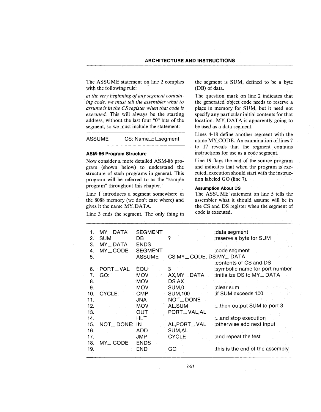
1. | MY _DATA | SEGMENT |
| ;data segment |
2. | SUM | DB | ? | ;reserve a byte for SUM |
3.MY_DATA ENDS
4. | MY_CODE | SEGMENT |
| ;code segment |
5. |
| ASSUME | CS:MY _CODE, DS:MY_ DATA | |
|
|
|
| ;contents of CS and DS |
6. | PORT_VAL | EQU | 3 | ;symbolic name for port number |
7. | GO: | MOV | AX,MY_DATA | ;initialize DS to MY_DATA |
8. |
| MOV | DS,AX |
|
9. |
| MOV | SUM,O | ;clear sum |
10. | CYCLE: | CMP | SUM,100 | ;if SUM exceeds 100 |
11. |
| JNA | NOT_DONE |
|
12. |
| MOV | AL,SUM | ;...then output SUM to port 3 |
13. |
| OUT | PORT _ VAL,AL |
|
14. |
| HLT |
| ;...and stop execution |
15. | NOT_DONE: | IN | AL,PORT _VAL | ;otherwise add next input |
16. |
| ADD | SUM,AL | ;and repeat the test |
17. |
| JMP | CYCLE | |
18.MY_CODE ENDS
19. | END | GO | ;this is the end of the assembly |