ARCHITECTURE AND INSTRUCTIONS
Register Operands
An instruction may address an operand resid- ing in one of the general registers or in one of the pointer or index registers. Fig.
Immediate Operands
In general, one of the two operands of a two- operand instruction can be "immediate" data contained within the. instruction~ These oper- ands are represented in
Addressing Mode Usage
The addressing modes were designed to per- mit efficient implementation of
The addressing modes involving the BP base register allow accessing data· in the stack segment instead of in the data segment. Rec- ursive procedures and
Addressing Summary
memory address. The 8088 Assembly lan- guage simplifies the task of selecting the desired addressing modes for use with basic 8088 instruction types.
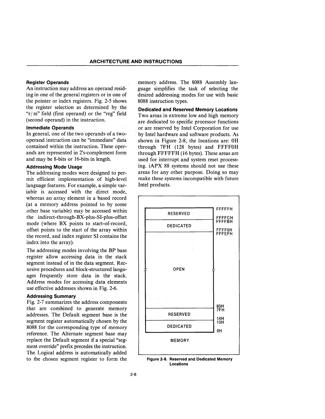
Dedicated and Reserved Memory Locations
Two areas in extreme low and high memory are dedicated to specific processor functions or are reserved by Intel Corporation for use by Intel hardware and software products. As shown in Figure
r------------, FFFFFH
RESERVED
r
FFFFBH
DEDICATED
r ----------..... FFFFOH
FFFEFH
OPEN
Fig. 2-7·summarizes the address Gomponents that are combined to generate memory addresses. The Default segment base is the segment register automatically chosen by the ;8088 for the corresponding type of memory reference. The Alternate segment base may replace the Default segment if a special "seg- ment override" prefix precedes the instruction. The Logical address is automatically.added to the chosen segment register to form the
BOH 7FH
RESERVED
14H
13H
DEDICATED
OH
MEMORY