HARDWARE DESIGN
These pins drive the next 8 address bits on the address bus. They are not multiplexed with other signals and are valid during the entire machine cycle.
These lines float to
A
A 16 through A 19 have two sets of functions. First, at the beginning of each machine cycle, these pins drive the upper 4 bits of the iAPX 88's
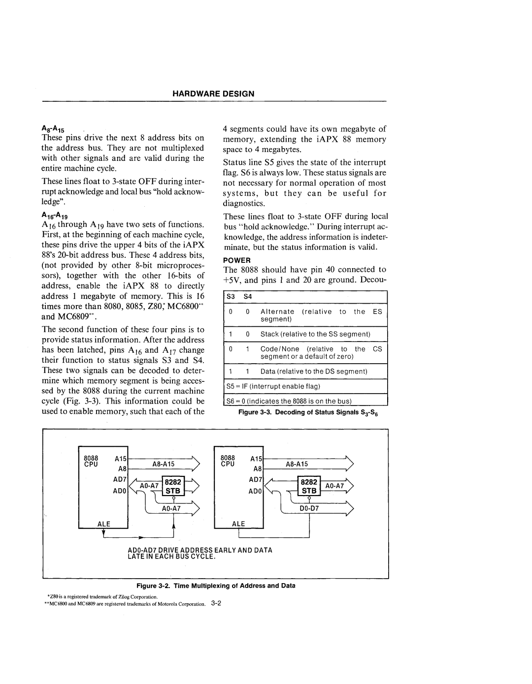
The second function of these four pins is to provide status information. After the address has been latched, pins AI6 and AJ7 change their function to status signals S3 and S4. These two signals can be decoded to deter- mine which memory segment is being acces- sed by the 8088 during the current machine cycle (Fig.
4 segments could have its own megabyte of memory, extending the iAPX 88 memory space to 4 megabytes.
Status line S5 gives the state of the interrupt flag. S6 is always low. These status signals are not necessary for normal operation of most systems, but they can be useful for diagnostics.
These lines float to
POWER
The 8088 should have pin 40 connected to +5V, and pins 1 and 20 are ground. Decou-
S3 S4
0 0 Alternate (relative to the ES segment)
10 Stack (relative to the SS segment)
01 Code/None (relative to the CS segment or a default of zero)
11 Data (relative to the OS segment)
S5 = IF (interrupt enable flag)
S6 = 0 (indicates the 8088 is on the bus)
Figure 3-3. Decoding 01 Status Signals S3-S6
8088 | A15r | 8088 | A151 | " | ||
CPU |
| A8·A15 | CPU |
| A8·A15 |
|
ALEALE
ADO·AD7DRIVE ADDRESS EARLY AND DATA
LATE IN EACH BUS CYCLE.
Figure 3-2. Time Multiplexing of Address and Data
*Z80 is a registered trademark of Zilog Corporation.
**MC6800 and MC6809 are registered trademarks of Motorola Corporation.
