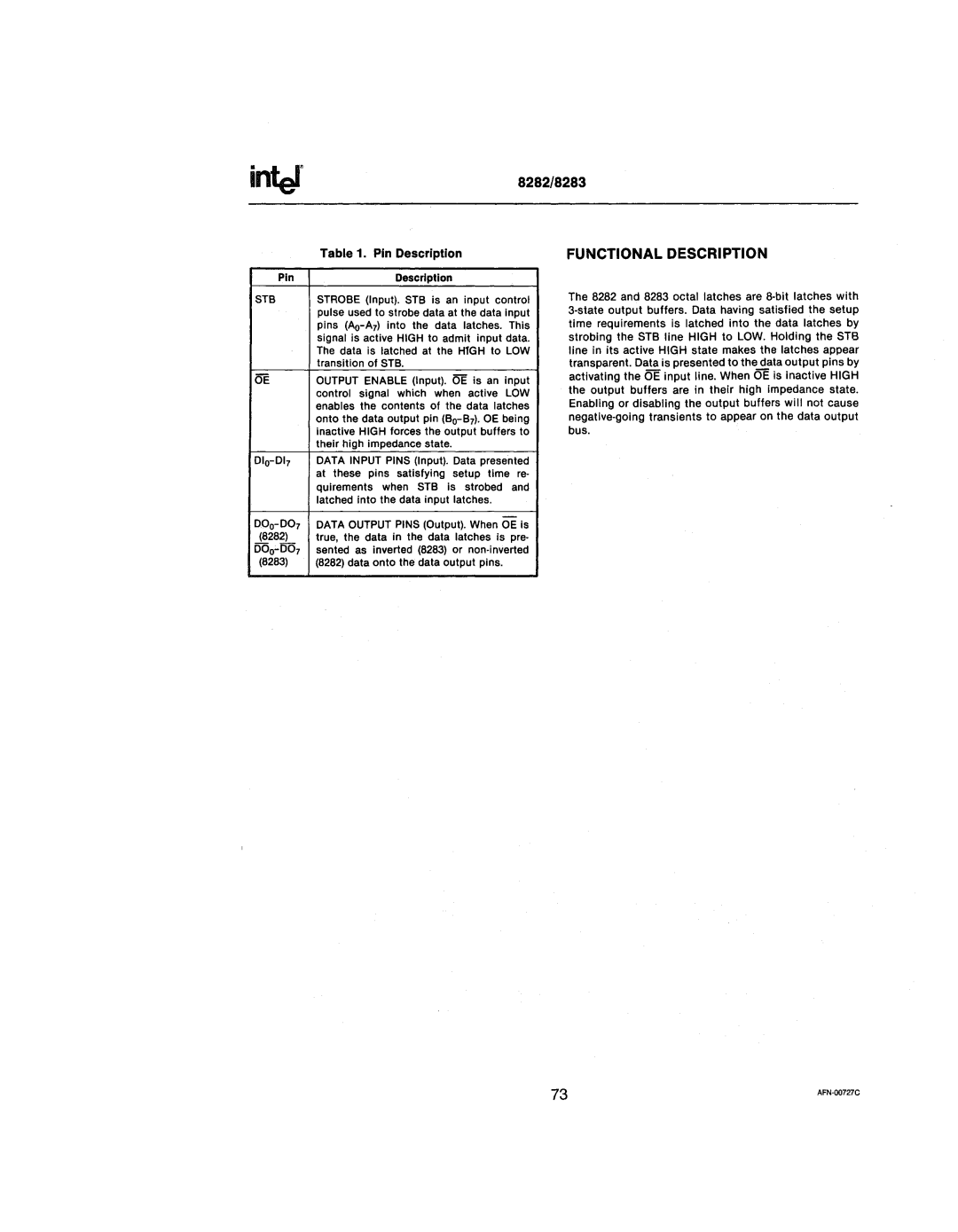
inter

Pin

8282/8283

Table 1. Pin Description

FUNCTIONAL DESCRIPTION

Description

STB

OE

010-017

STROBE (Input). STB is an input control pulse used to strobe data at the data input pins (Ao-A7) into the data latches. This signal is active HIGH to admit input data. The data is latched at the HfGH to LOW transition of STB.

OUTPUT ENABLE (Input). i5E is an input control signal which when active LOW enables the contents of the data latches onto the data output pin (Bo-B7). OE being Inactive HIGH forces the output buffers to their high impedance state.

DATA INPUT PINS (Input). Data presented at these pins satisfying setup time re- quirements when STB Is strobed and latched into the data input latches.

The 8282 and 8283 octal latches are 8·bit latches with 3-state output buffers. Data having satisfied the setup time requirements is latched into the data latches by strobing the STB line HIGH to LOW. Holding the ST8 line in its active HIGH state makes the latches appear transparent. Data is presented to the data output pins by activating the OE input line. When OE is inactive HIGH the output buffers are in their high impedance state. Enabling or disabling the output buffers wili not cause negative-going transients to appear on the data output bus.

090- 007

(8282)

000:..007

(8283)

DATA OUTPUT PINS (Output). When OE Is true, the data in the data latches is pre· sented as Inverted (8283) or non·inverted (8282) data onto the data output pins.

73

AFN-D0727C


Page 342
Image 342
Intel 210200-002 manual Inter