ARCHITECTURE AND INSTRUCTIONS
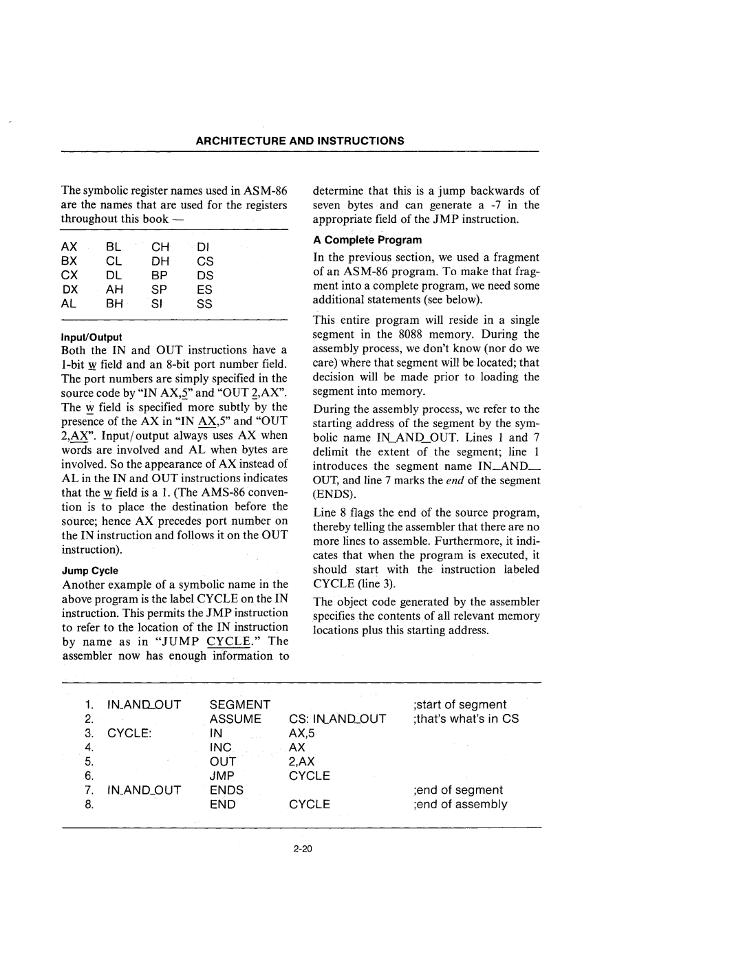
The symbolic register names used in
AX | BL | CH | 01 |
BX | CL | OH | CS |
CX | OL | BP | OS |
DX | AH | SP | ES |
AL | BH | SI | SS |
InpuVOutput
Both the IN and OUT instructions have a
Jump Cycle
Another example of a symbolic name in the above program is the label CYCLE on the IN instruction. This permits the JMP instruction to refer to the location of the IN instruction by name as in "JUMP CYCLE." The assembler now has enough information to
determine that this is a jump backwards of seven bytes and can generate a
A Complete Program
In the previous section, we used a fragment of an
This entire program will reside in a single segment in the 8088 memory. During the assembly process, we don't know (nor do we care) where that segment will be located; that decision will be made prior to loading the segment into memory.
During the assembly process, we refer to the starting address of the segment by the sym- bolic name IN_AND_OUT. Lines I and 7 delimit the extent of the segment; line 1 introduces the segment name IN_AND_ OUT, and line 7 marks the end of the segment (ENDS).
Line 8 flags the end of the source program, thereby telling the assembler that there are no more lines to assemble. Furthermore, it indi- cates that when the program is executed, it should start with the instruction labeled CYCLE (line 3).
The object code generated by the assembler specifies the contents of all relevant memory locations plus this starting address.
1. | IN_ANQOUT | SEGMENT |
| ;start of segment |
2. |
| ASSUME | CS: I~ANO_OUT | ;that'swhat'sin CS |
3. | CYCLE: | IN | AX,5 |
|
4. |
| INC | AX |
|
5. |
| OUT | 2,AX |
|
6. |
| JMP | CYCLE |
|
7. IN_AN~_OUT | ENDS |
| ;end of segment | |
8. |
| END | CYCLE | ;end of assembly |
