HARDWARE DESIGN
Before calling the corresponding interrupt routine, the CPU saves the machine status by pushing the flag's register onto the stack.
The CPU then clears the interrupt enable and trap bits in the flag's register to prevent sub- sequent maskable and
Bus Control Transfer
In most iAPX 88 designs, the system busses are normally controlled by the 8088 CPU. This means that address and control signals are driven by the 8088, and that data is driven by the 8088 or by a device being read by the 8088.
HOLD AND HLDA
In some cases, however, another device can take control of the system bus and drive it while the 8088 is forced into the inactive state, called "HOLD".
configuration in which the HOLD/ HLDA sequence would be used.
The handshake timing for transfer of bus control is shown in Figure
Maximum Mode Systems
In addition to the minimum mode systems described, the iAPX 88 can also be config- ured in the maximum mode.
Maximum mode systems are intended prim- arily for larger
SIGNALCONDITION
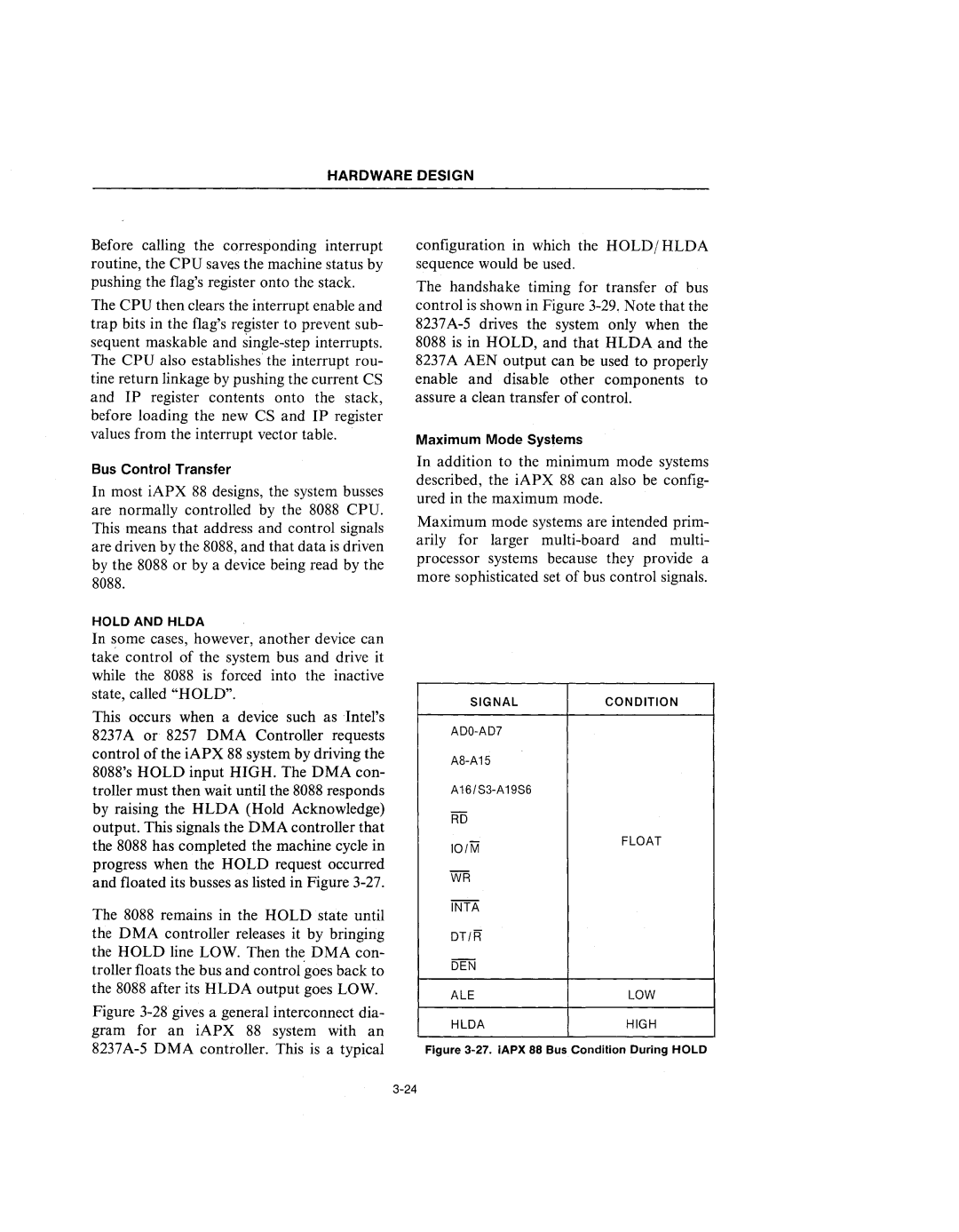
This occurs when a device such as Intel's 8237A or 8257 DMA Controller requests control of the iAPX 88 system by driving the 8088's HOLD input HIGH. The DMA con- troller must then wait until the 8088 responds by raising the HLDA (Hold Acknowledge)
output. This signals the DMA controller that the 8088 has completed the machine cycle in progress when the HOLD request occurred and floated its busses as listed in Figure
The 8088 remains in the HOLD state until
RD
101M
WR
INTA
FLOAT
the DMA controller releases it by bringing the HOLD line LOW. Then the DMA con- troller floats the bus and control goes back to the 8088 after its HLDA output goes LOW.
Figure 3-28 gives a general interconnect dia- gram for an iAPX 88 system with an 8237A-5 D MA controller. This is a typical
DT/R
DEN
ALELOW
HLDAHIGH