ARCHITECTURE AND INSTRUCTIONS
instruction. This instruction allows the pro- cessor to synchronize itself with external hardware.
Processor Escape
The ESC instruction provides a mechanism by which other processors (such as the Numeric Processor Extension) may receive their instructions from the 8088 instruction stream and make use of the 8088 addressing modes. The 8088 processor does no opera- tion for the ESC instruction other than to access a memory operand.
Bus Lock
A special
Single Step
INSTRUCTION TIMINGS
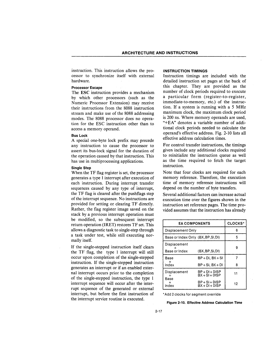
Instruction timings are included with the detailed instruction set pages at the back of this chapter. They are provided as the number of clock periods required to execute
aparticular form
For control transfer instructions, the timings given include any additional clocks required to reinitialize the instruction queue as well as the time required to fetch the target instruction.
When the TF flag register is set, the processor generates a type 1 interrupt after execution of each instruction. During interrupt transfer sequences caused by any type of interrupt, the TF flag is cleared after the pushflags step ofthe interrupt sequence. No instructions are provided for setting or clearing TF directly. Rather, the flag register image saved on the stack by a previous interrupt operation must be modified, so the subsequent interrupt
Note that four clocks are required for each memory reference. Therefore, the execution time of memory reference instructions will depend on the number of byte transfers.
Several additional factors can increase actual execution time over the figures shown in the instruction set reference pages. The time pro- vided assumes that the instruction has already
return operation (IRET) restores TF set. This allows a diagnostic task to
If the
EA COMPONENTS
Displacement Only
Base or Index Only (BX,BP,SI,DI)
Displacement |
|
+ | (BX,BP,SI,DI) |
Base or Index | |
Base | BP+DI, BX+SI |
+ | BP+SI, BX+DI |
Index | |
Displacement | BP+ DI+ DISP |
+ | BX+SI+DISP |
Base | BP+SI+DISP |
+ | |
Index | BX+DI+DISP |
CLOCKS·
6
5
9
7
8
11
12
interrupt, but before the first instruction of the interrupt service routine is executed.
*Add 2 clocks for segment override
