iAPX 88/10
FUNCTIONAL DESCRIPTION
Memory Organization
The processor provides a
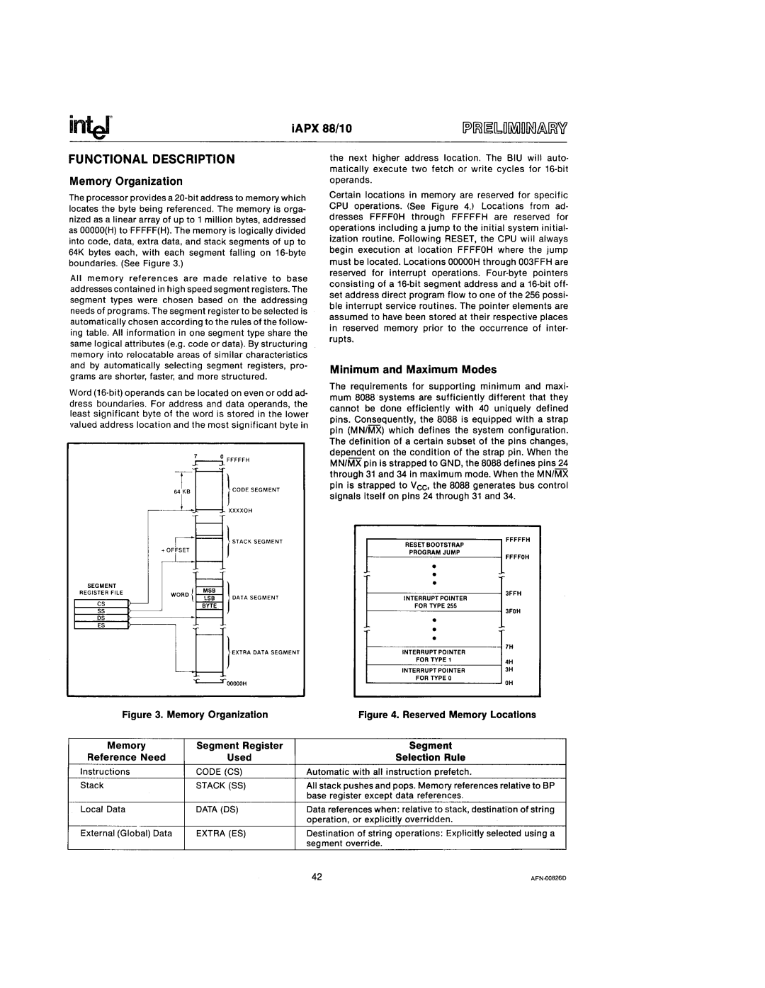
All memory references are made relative to base addresses contained in high speed segment registers. The segment types were chosen based on the addressing needs of programs. The segment register to be selected is automatically chosen according to the rules of the follow- ing table. All information in one segment type share the same logical attributes (e.g. code or data). By structuring memory into relocatable areas of similar characteristics and by automatically selecting segment registers, pro- grams are shorter, faster, and more structured.
Word (16·bit)operands can be located on even or odd ad· dress boundaries. For address and data operands, the least significant byte of the word is stored in the lower valued address location and the most significant byte in
0FFFFFH
.L Iroo> '''"'"'
r----~ XXXXOH
the next higher address location. The BIU will auto· matically execute two fetch or write cycles for 16·bit operands.
Certain locations in memory are reserved for specific CPU operations. (See Figure 4,) Locations from ad· dresses FFFFOH through FFFFFH are reserved for operations including a jump to the initial system initial· ization routine. Following RESET, the CPU will always begin execution at location FFFFOH where the jump must be located. Locations OOOOOH through 003FFH are reserved for interrupt operations. Four·byte pointers conSisting of a 16·bitsegment address and a 16·bitoff· set address direct program flow to one of the 256 possi· ble interrupt service routines. The pointer elements are assumed to have been stored at their respective places in reserved memory prior to the occurrence of inter· rupts.
Minimum and Maximum Modes
The requirements for supporting minimum and maxi· mum 8088 'systemsare sufficiently different that they cannot be done efficiently with 40 uniquely defined pins. Consequently, the 8088 Is equipped with a strap pin (MN/MX) which defines the system configuration. The definition of a certain subset of the pins changes, dependent on the condition of the strap pin. When the MN/MX pin is strapped to GND, the 8088 defines pins 24 through 31 and 34 In maximum mode. When the MN/MX pin is strapped to Vcc, the 8088 generates bus control signals itself on pins 24 through 31 and 34.
I
| r | F== } STACK SEGMENT | RESET BOOTSTRAP | FFFFFH |
| + OFrSET |
| PROGRAM JUMP | FFFFOH |
|
|
| • | |
|
|
|
| |
|
| f | • |
|
SEGMENT |
| ~ | • |
|
REGISTER FilE |
|
| 3FFH | |
WORO{ | INTERRUPT POINTER | |||
|
| } DATA SEGMENT |
| |
CS | I/ | i BYTE | FOR TYPE 255 | 3FOH |
SS |
|
| • | |
ES |
|
|
| |
OS |
|
| • |
|
|
| t |
| |
|
|
| • | 7H |
|
| }EXTRA DATA SEGMENT | INTERRUPT POINTER | |
|
|
| ||
|
|
| FOR TYPE 1 | 4H |
|
|
|
| |
|
|
| INTERRUPT POINTER | 3H |
|
| FOR TYPE 0 | OH | |
|
|
| ||
Figure 3. Memory Organization | Figure 4. Reserved Memory Locations | |||
Memory | Segment Register | Segment |
| |
Reference Need | Used | Selection Rule |
| |
Instructions | CODE (CS) | Automatic with all instruction prefetch. |
| |
Stack |
| STACK (SS) | All stack pushes and pops. Memory references relative to BP | |
|
|
| base register except data references. |
|
Local Data |
| DATA (OS) | Data references when: relative to stack, destination of string | |
|
|
| operation, or explicitly overridden. |
|
External (Global) Data | EXTRA (ES) | Destination of string operations: Explicitly selected using a | ||
|
|
| segment override. |
|
|
|
| 42 | |