HARDWARE DESIGN
Pins with different functions in mmlmum and maximum modes are listed in Fig.
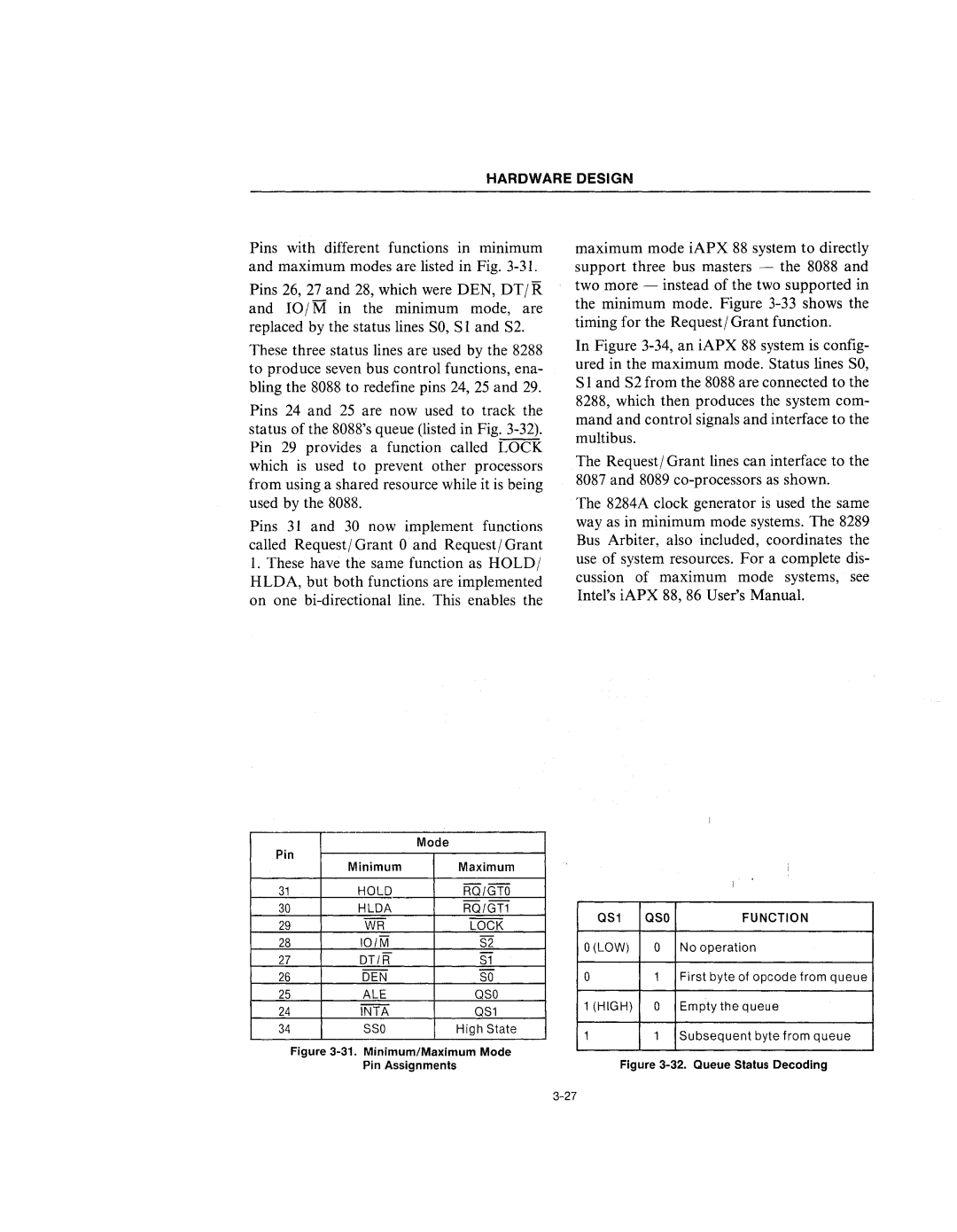
Pins 26, 27 and 28, which were DEN, DT j R and IOjM in the minimum mode, are replaced by the status lines SO, S 1 and S2.
These three status lines are used by the 8288 to produce seven bus control functions, ena- bling the 8088 to redefine pins 24, 25 and 29.
Pins 24 and 25 are now used to track the status of the 8088's queue (listed in Fig.
Pins 31 and 30 now implement functions called Requestj Grant 0 and Requestj Grant
1.These have the same function as HOLDj HLDA, but both functions are implemented on one
maximum mode iAPX 88 system to directly support three bus masters - the 8088 and two more - instead of the two supported in the minimum mode. Figure
In Figure
The Requestj Grant lines can interface to the 8087 and 8089
The 8284A clock generator is used the same way as in minimum mode systems. The 8289 Bus Arbiter, also included, coordinates the use of system resources. For a complete dis- cussion of maximum mode systems, see Intel's iAPX 88, 86 User's Manual.
| Mode |
|
|
|
| |
Pin |
|
|
|
| ||
| Minimum | Maximum |
|
|
| |
31 | HOLD | RO/GTO |
|
|
| |
30 | HLDA | RO/GT1 | OS1 | osa | FUNCTION | |
29 | WR | LOCK | ||||
|
|
| ||||
28 | 101M | S2 | O(LOW) | 0 | No operation | |
27 | DT/R | S1 | ||||
|
|
| ||||
26 | DEN | SO | 0 | 1 | First byte of opcode from queue | |
25 | ALE | OSO | 1 (HIGH) | 0 | Empty the queue | |
24 | INTA | OS1 | ||||
|
|
| ||||
34 | SSO | High State | 1 | 1 | Subsequent byte from queue | |
|
|
| ||||
| Figure | Figure | ||||
| Pin ASSignments |
| ||||