HARDWARE DESIGN
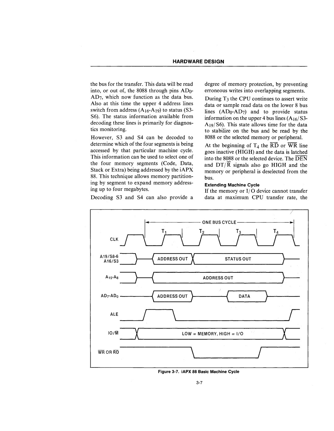
the bus for the transfer. This data will be read into, or out of, the 8088 through pins ADo- AD?, which now function as the data bus. Also at this time the upper 4 address lines switch from address
However, S3 and S4 can be decoded to determine which of the four segments is being accessed by that particular machine cycle. This information can be used to select one of the four memory segments (Code, Data, Stack or Extra) being addressed by the iAPX
88.This technique allows memory partition- ing by segment to expand memory address- ing up to four megabytes.
Decoding S3 and S4 can also provide a
degree of memory protection, by preventing erroneous writes into overlapping segments.
During T3 the CPU continues to assert write data or sample read data on the lower 8 bus lines
At the beginning of T4 the RD or WR line goes inactive (HIGH) and the data is latched into the 8088 or the selected device. The DEN and DT/R: signals also go HIGH and the memory or peripheral is deselected from the bus.
Extending Machine Cycle
If the memory or 110 device cannot transfer data at maximum CPU transfer rate, the
/
CLK
A16/S3 | STATUS OUT | |||
~ ADDRESS OUT X | } | |||
~ |
| ADDRESS OUT | } - | |
ADrADo --------t( ADDRESS OUT | ||||
ALE | / |
| ||
|
|
| ||
101M ~~ | L_O_W_=_M_E_M_O_R_Y_,H_I_G_H_=_I/_O______L | |||
WR OR RD |
|
| |
| Figure |