14.Replace any adapters that you removed (see “Installing an adapter” on page 82); then, install the side cover (see “Installing the side cover” on page 79).
15.Lock the side cover if it was unlocked during removal.
16.Reconnect the external cables and power cords; then, turn on the attached devices and turn on the server.
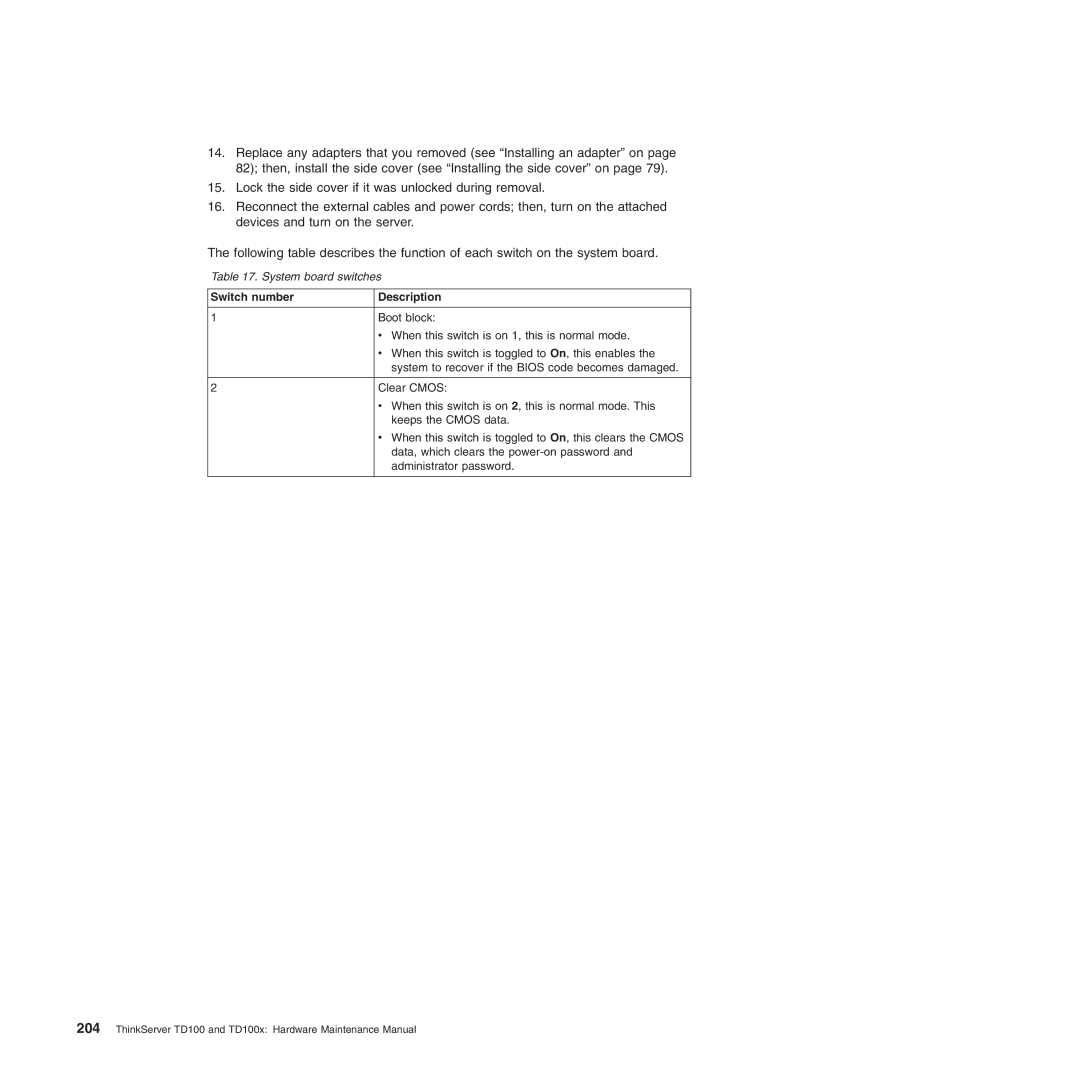
The following table describes the function of each switch on the system board.
Table 17. System board switches
Switch number | Description |
|
|
1 | Boot block: |
| v When this switch is on 1, this is normal mode. |
| v When this switch is toggled to On, this enables the |
| system to recover if the BIOS code becomes damaged. |
|
|
2 | Clear CMOS: |
| v When this switch is on 2, this is normal mode. This |
| keeps the CMOS data. |
| v When this switch is toggled to On, this clears the CMOS |
| data, which clears the |
| administrator password. |
|
|